Warning


Close

Confirm Action

Are you sure you wish to do this?

Confirm Cancel
BCM
User Panel

Page AK-47 » Optics & Accessories
AK Sponsor: palmetto
Site Notices
Posted: 3/2/2023 2:10:28 AM EDT

You might ask, "what's a Pong 5; some kind of video game??"  I wouldn't blame you if you did because this thing is pretty obscure.  But no, it's not a video game.  The PON-5 (Optical Night Sight-5 in English) is an obscure 1990's Russian made, compact, lightweight, night vision optic.  Those of you that are aware of this unit already know that there is pretty much zero information available online.  If that's you, you're probably going to enjoy what follows.  If you're one of the vast majority of people who have no idea what I'm on about, read on because you might enjoy this too.....if you enjoy my usual articles that drone on and on about the smallest details of the most mundane things.  The entirety of this article will consist of several posts so check back in over the next several days for all of it.  I'll let you know when I've finished.  Okiedokie, let's begin, shall we?


Below is the topic of this article, the PON-5, along with some of the kit it originally left the factory with back in 1996:


Although this unit was designed for the Russian military, this picture shows it was clearly also available on the commercial market.  Although the carry bag is a strong indicator of this fact, it will become abundantly clear when we look at the manual.  So, what are we looking at here?  Starting at the top left and moving down, we have a plastic bag for storing the lens cleaning cloth.  Just below that is said cloth.  Below that, we have a piece of paper that was folded up in the bag with the lens cleaning cloth.  It has cyrillic writing on it that I am clueless about.  At the middle top is a 1' ruler I put in the shot for scale with the scope and it's carry bag below.  At the extreme right is the rather tattered manual.  It's numbered to the scope so I know it's the original.  Although this entire kit has clearly seen very little to no use, the manual looks rather rough because, to put it bluntly, it's made of very low quality paper and card stock.  I mean, it's laughable.  Fortunately, the scope itself seems to be as robustly made as any Soviet era unit I've encountered.  


The lens cleaning cloth and its storage bag:


Not much to say here other than it's a yellow cloth used to wipe down the lens in a pinch.  Best to leave it in its bag for posterity and use something else of known Quality.  Does anybody use the cloth that came with their optic?  I don't.


The mystery piece of paper that was also in the bag:


Whether this came with it from the factory or somehow made its way in there over the past 26+ years I cannot say but I assume it's the latter.


Logo on the bag:


"Kronos" was/is one of the commercial trade names used at that time by the Zagorsk Optical Mechanical Plant headquartered at Sergiyev Posad, just outside Moscow.  They've been making both military and civilian optical equipment since the 1930's and they're still at it today.  They also go by "ZOMO" in some markets.


Inside of the bag:


The bag is made of a heavy duty leatherette lined with a felt type material and is reinforced at stress points by welting.  It's not fancy but it is sturdy.


Detail shot of the zipper pull and an attachment point for a shoulder strap.  The strap, if ever present, is now missing.


The other strap attachment point:


A general left side view of the scope itself:


So, what are we looking at here?  Lots of neato things.  If you're not familiar with Soviet/Russian NV optics, this might look complicated but it's not, I assure you.  You have to remember that it was designed for infantry use in combat.  To that end, it's simple to use, robust and generally efficient in its adjustments.  At the moment, I'll just introduce you to what we're looking at in the most general way.  Later, we'll l go into detail on each feature as we look at it more closely.  

    --  To the left of frame is the objective lens.  Currently, it has the light filter or diaphragm in place.  This is used to regulate how much light is allowed into the unit during use in daylight or dusk.  Too much light will destroy the internal image intensifier while too little will not allow the unit to properly define the image.  We'll get into that later.

    --  Moving toward the rear, we come to a roughly "T" shaped thingee hanging on the side of the body.  That's the windage and elevation adjustment mechanism.

    --  Below that, we see a flat head screw.  That's the locking screw for the battery compartment door.

    --  The bronze/tarnished brass looking knob is the on/off switch and it also adjusts reticle intensity.

    --  Below that is the clamping mechanism used to hold the unit fast to the scope rail on the rifle.

    --  The main body of the unit is where we see the writing.  Inside there is the intensifier tube and electronics.

    --  The entire unit is made of some type of nonferrous alloy and is covered in a very durable dark grey hammertone paint.  This was the preferred finish for Russian/Soviet optics going back decades and it varies from a light grey to almost black.  

    --  At the far right of frame is the rubber eyecup covering the ocular lens.


General right side view:


Notice that there are six flat head screws in a roughly rectangular pattern on the main body.  These attach the clamping mechanism to the scope body.  In this way, the clamping mechanism can be removed and replaced by another mechanism for mounting on things other than a rifle.  Normally, they are never removed though as the intended mounting clamp would be installed at the factory during manufacture thus mating the unit to a particular class of weapon (e.g. rifle, machine gun, whatever else crazy Ivan dreamed up to use it on).


Alrighty, that's enough to get started.  In the next installment, we'll begin looking at things more closely and I'll tell you my thoughts on the what and why of the various bits.  I say "my thoughts" because you have to remember, other than a few "look at what I have" pictures online, there is literally NOTHING out there for research purposes and there are probably no more than a handful of these units in the United States.  What I'm typing in these posts is going to be pretty much all there is as of this date.  So, I can only tell you what I see and think based on what I have in front of me and extrapolate from my personal experience with a number of other Soviet and early post Soviet units I've been fortunate enough to play with and take to the range over the years.  As such, I can't absolutely guarantee that I'll get it all right but I can promise you I'll do my best. With that, I'll sign off for the night and I'll see you back here soon.  Thanks for joining me!
Link Posted: 3/6/2023 1:13:42 AM EDT
[#1]
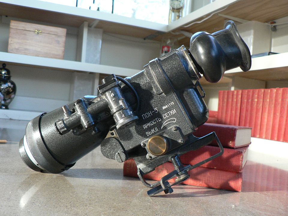
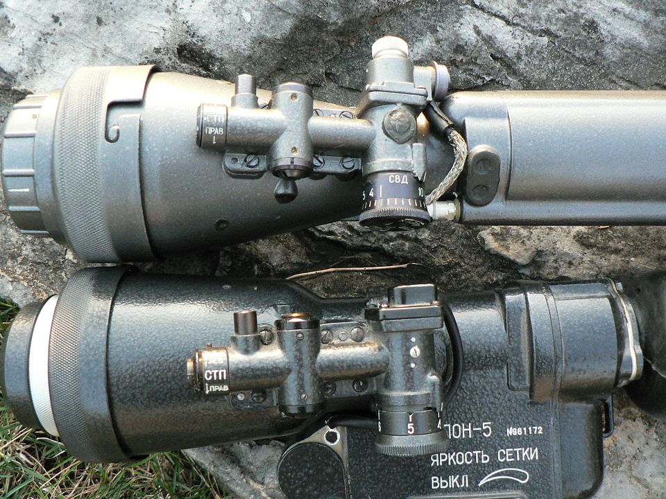
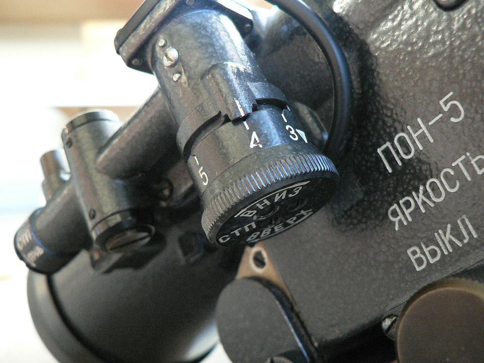
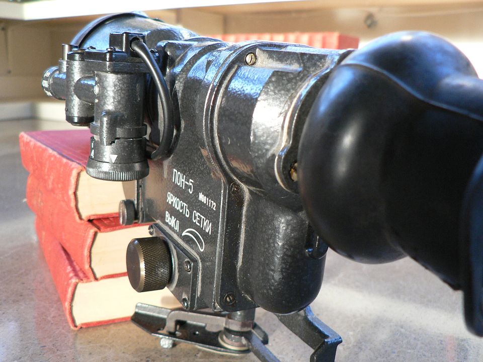
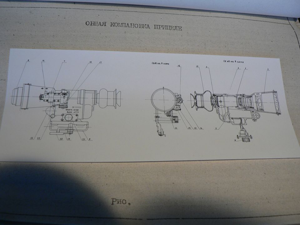
Alrighty, next we're going to look at the removeable light filter and objective lens block.


Mounted over the objective lens is an adjustable light filter with an iris that works exactly like the aperture on a camera lens:


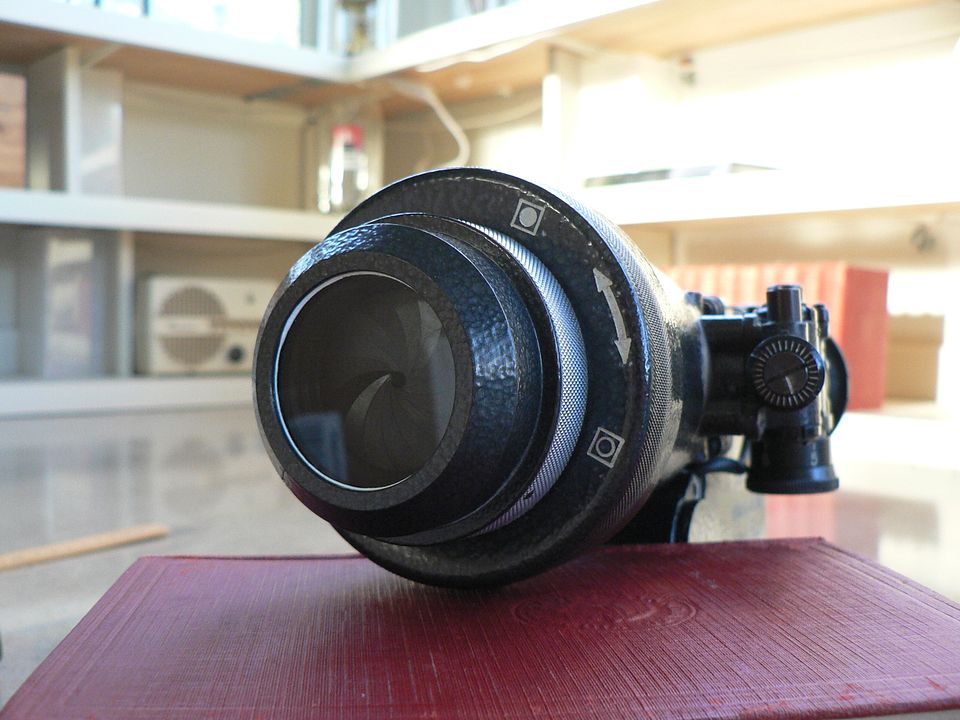
Viewed from the front, turning the adjustment ring clockwise opens the iris, allowing more light into the scope.  Obviously, turning the adjustment ring counterclockwise limits the light.  


IMPORTANT:

This filter should ALWAYS be mounted and the iris FULLY CLOSED when the unit is put into storage, powered up, used in anything other than nighttime conditions, and left in place after powering down for at least a half hour because the intensifier tube takes a while to discharge after being switched off.  If these instructions are not followed, you will, at a minimum, greatly decrease the life of the intensifier tube.  At worst, you'll render it inoperable.  THINK before you touch ANY of the controls on this scope.  Not doing so can really ruin your day.


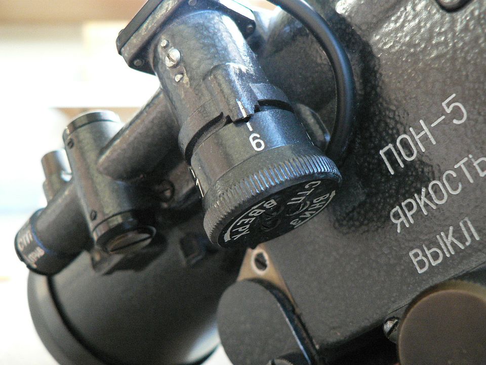
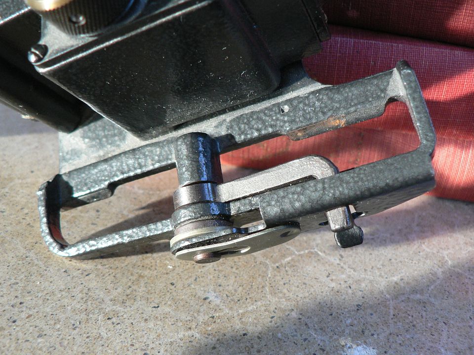
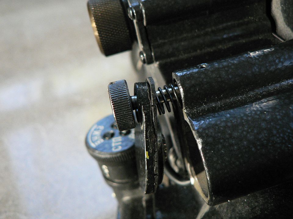
The filter is held in place on the scope via two bayonet mounts located 180 degrees from each other:


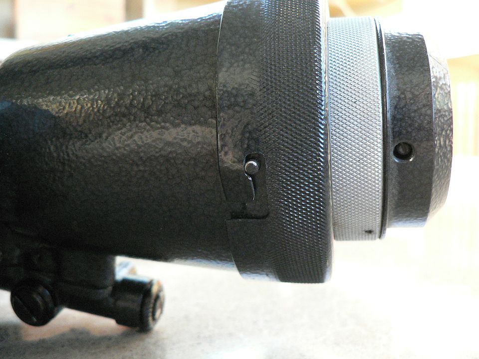
This one is a little distorted and needs a little TLC:


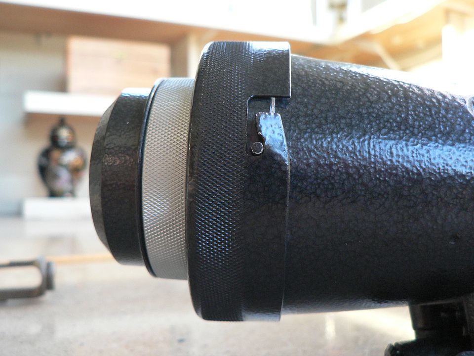
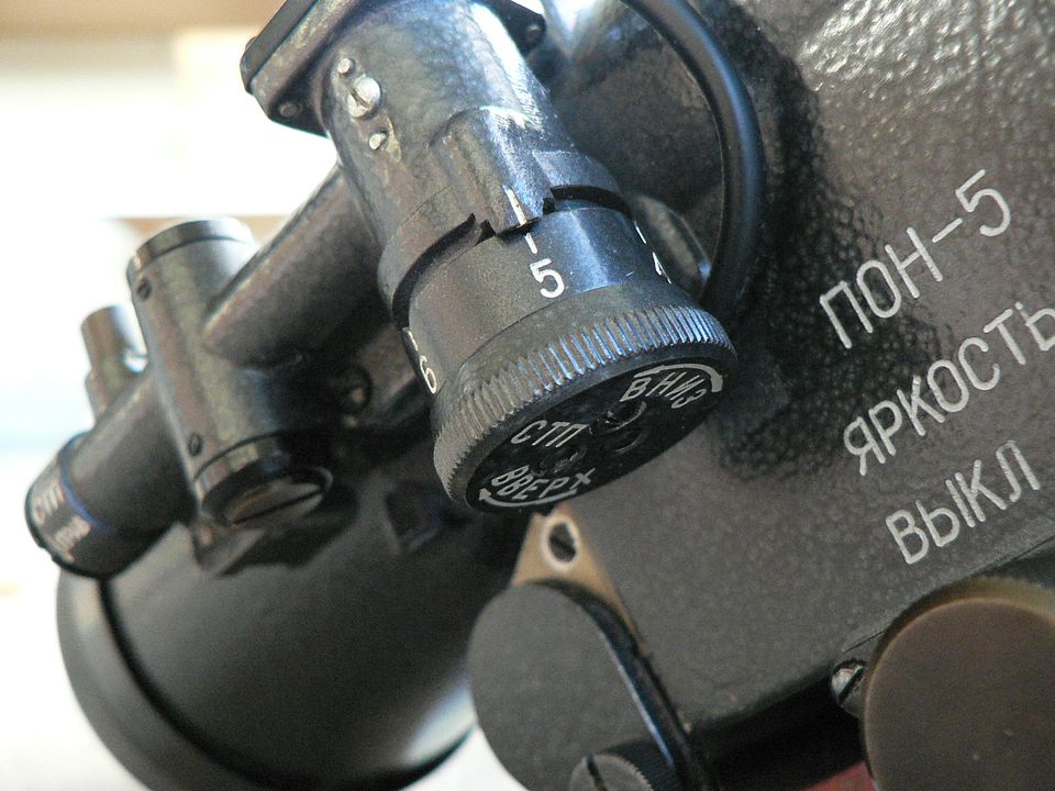
The knurled painted part is used to grip the filter when mounting/dismounting from the scope while the knurled unpainted part is used to adjust the iris.  

To dismount the filter when viewed from the front, you grip the painted knurled surface, push to the rear, rotate the filter clockwise until it stops, and pull the filter forward.  

To mount the filter when viewed from the front, grip it by the painted knurled surface, line up the pins on the scope body with the slots on the filter body, push to the rear until the pins bottom out in the slots, rotate the filter counterclockwise until it stops, and release.  

After mounting the filter, ensure that the iris is fully closed.


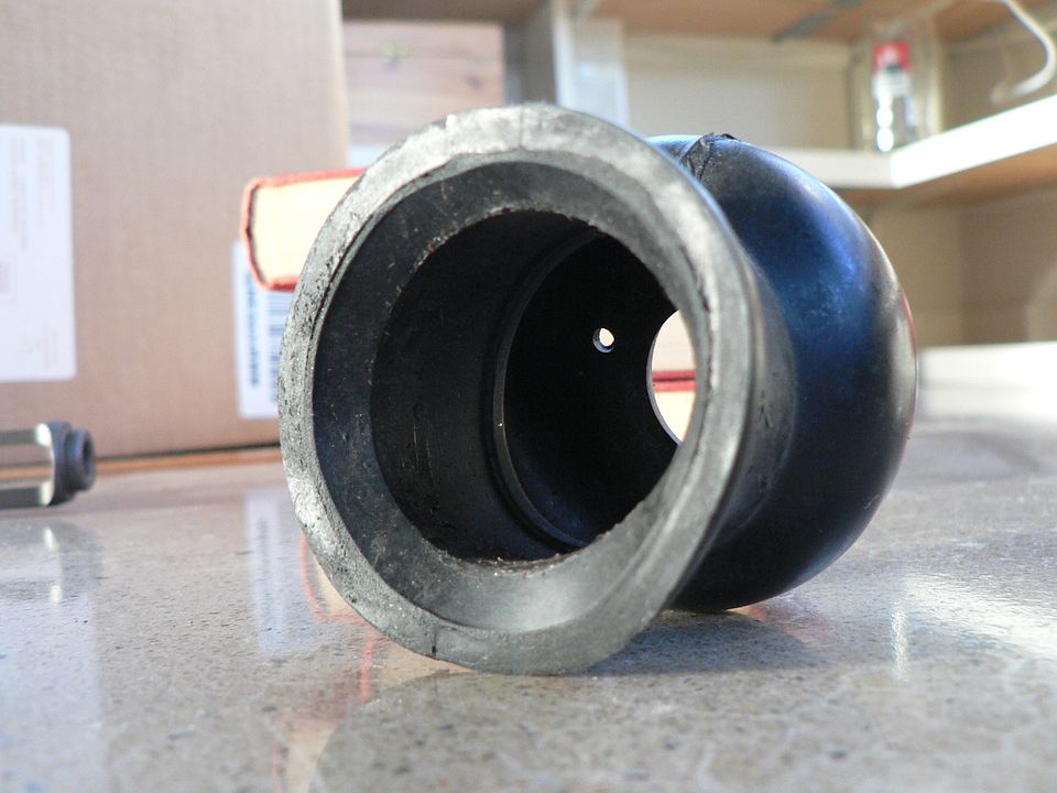
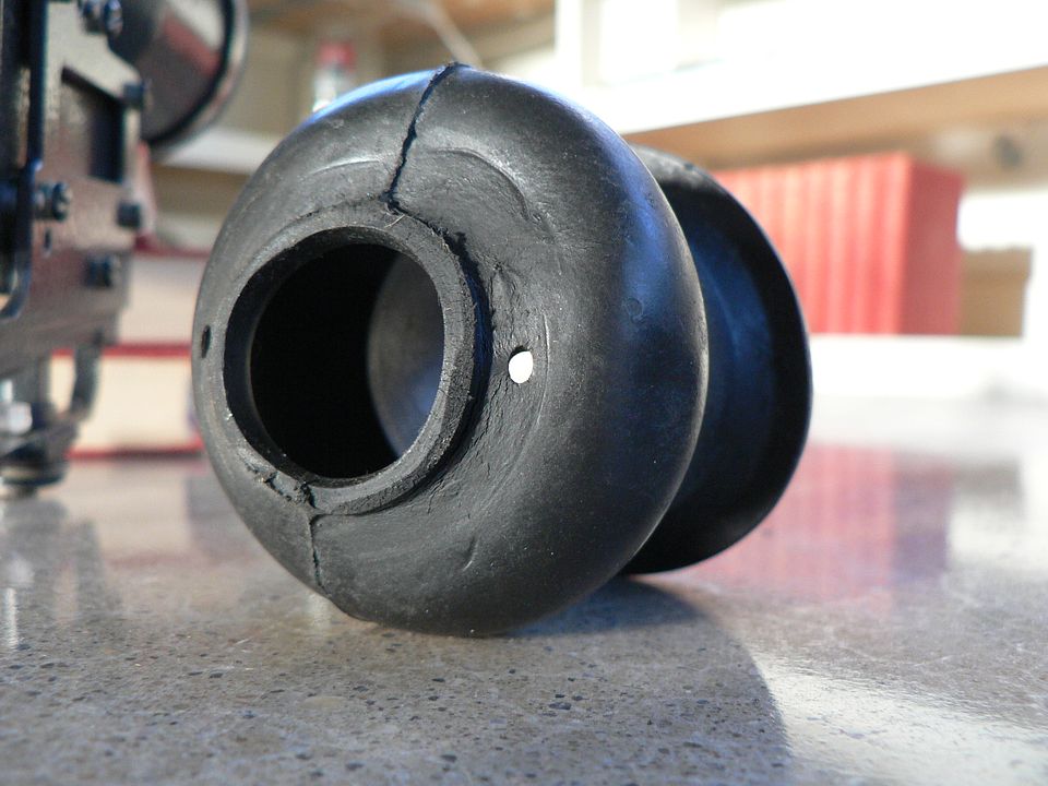
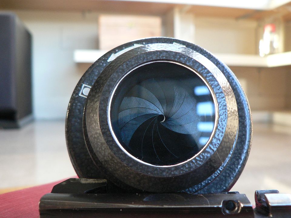
Here, we've removed the filter and we're looking at it from the rear with the iris fully open.


What we're looking at is a spring plate that serves to keep tension on the filter when mounted.  Without this, the filter would rattle and easily fall off the scope.  

Around the outer edge of the spring plate is a rubber gasket bonded to the plate.  This helps keep rain out and does double duty acting as a grippy surface as additional insurance against the filter rotating and falling off.  


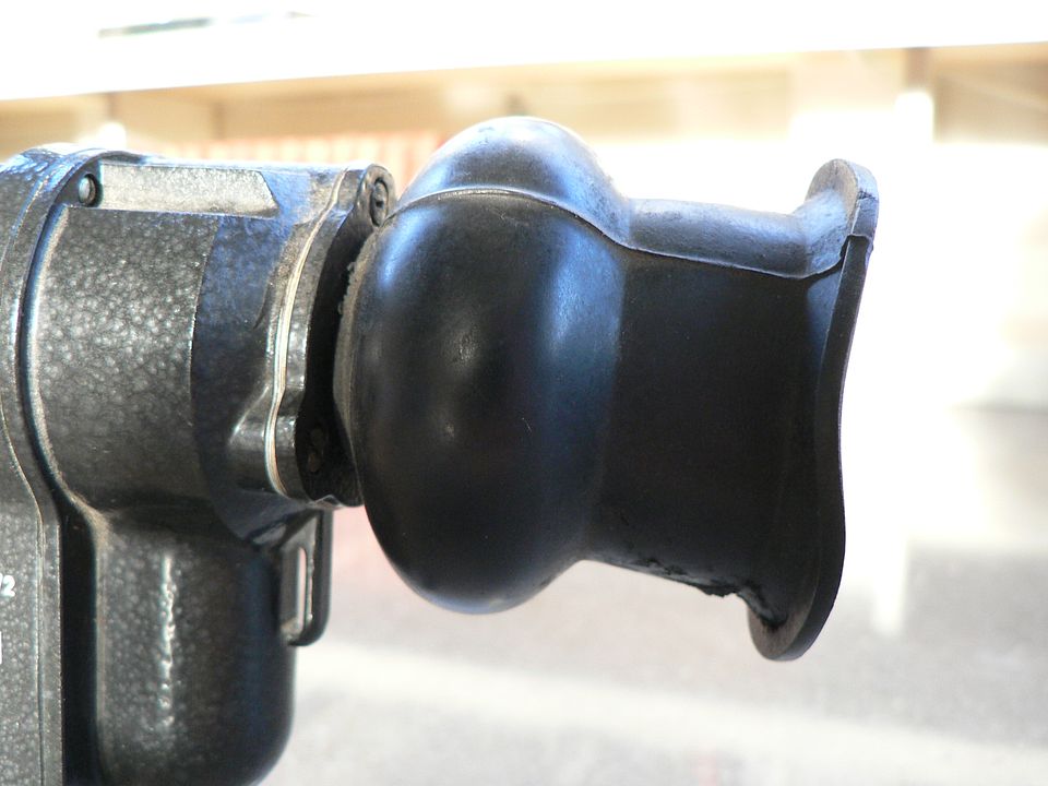
A general side view of the filter removed showing the knurling detail and hammertone finish:


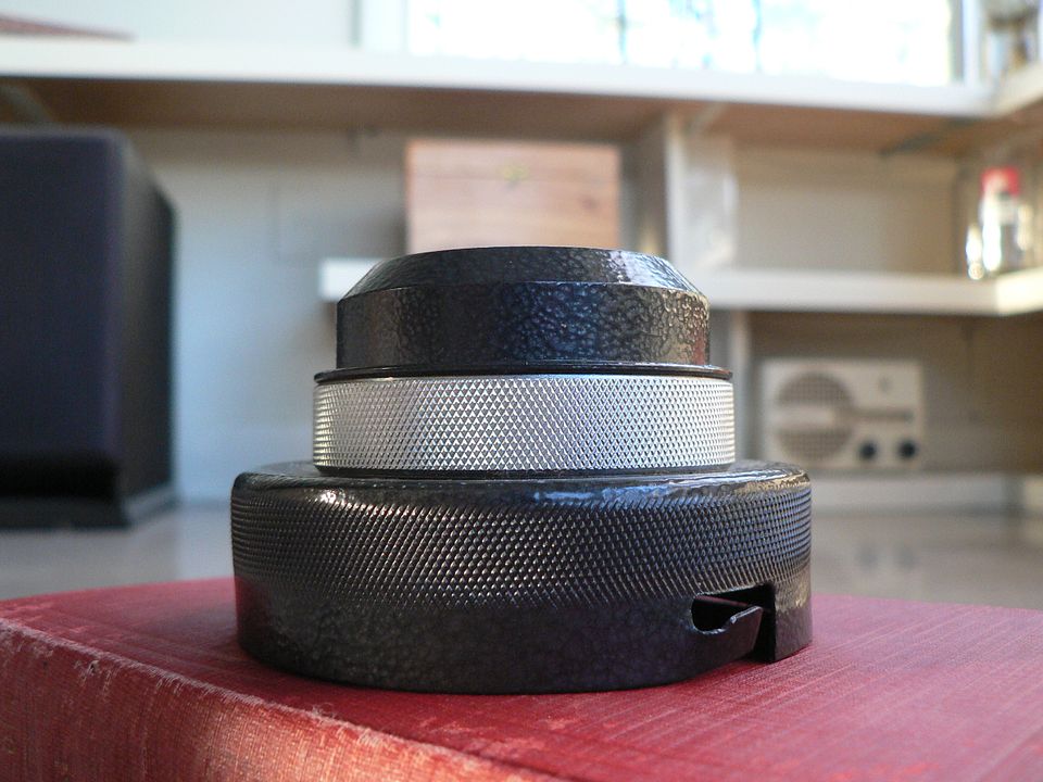
Here, we see the filter removed from the scope and the iris fully closed:


Note the large number of vanes.  Also notice that there is just the smallest crescent of light shining through the center of the iris.  The reason it's not round will be apparent in the next photograph.  


?The iris partially opened:


There are no click stops when opening this up.  It's infinitely variable from fully closed to fully opened.  

Notice the little tab protruding into the opening at about the 10 o'clock position.  This is the reason why you see a crescent of light instead of a round hole when the iris is fully closed.  The idea is to absolutely minimize the amount of light entering the scope to protect the intensifier tube if switched on in a bright setting.  


Fully opened:


?Notice that the glass is grey like sun glasses.  That's the point.  We're looking through two neutral density filters.


So, how do you properly use this filter?

No matter when you use this scope, from the noon day sun to the darkest of night, the object is to feed the image intensifier tube only the minimal amount of light necessary for it to do it's job, not one photon more.  Too little light, and you won't get a useful image.  To much light and the you'll burn out the tube.  

So, no matter the time of day or night, you power the unit on with the filter mounted and the iris fully closed.  Then, you SLOWLY open the filter until you get a useful image.  There are no set in stone parameters here because there are many variables.  Some of these variables are, the brightness of the sun, the brightness of the moon, how cloudy the sky is, haze, open field or forest setting, ambient light at night, and probably others that escape me at the moment.  Experience is the best teacher here.  

If a useful image cannot be obtained with the filter full opened, only then do you remove it and expose the objective lens to the elements.  But keep the filter handy as conditions can change rapidly and you might need to reinstall it in a hurry, even at night.


Just remember, every single photon that enters the objective lens degrades the intensifier tube a little bit.  That tube has a service life.  How long that life is is directly proportional to how much light you expose it to. If I sound like I'm nagging, it's because I am.  I cannot overstress how careful you need to be.  As you can imagine, replacement parts are impossible to find and one screw up will destroy the tube.


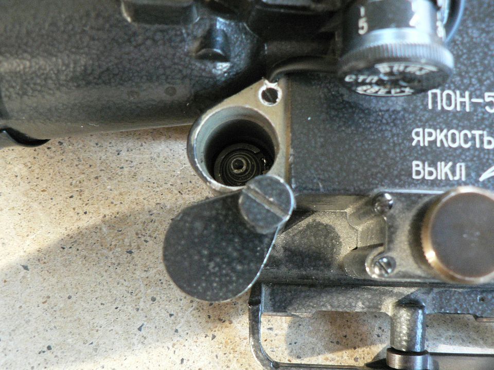
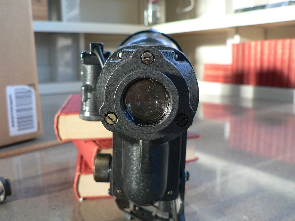
Here is the objective lens with the filter removed:


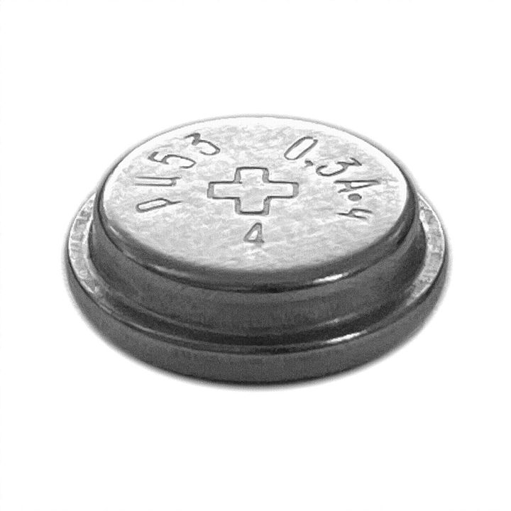
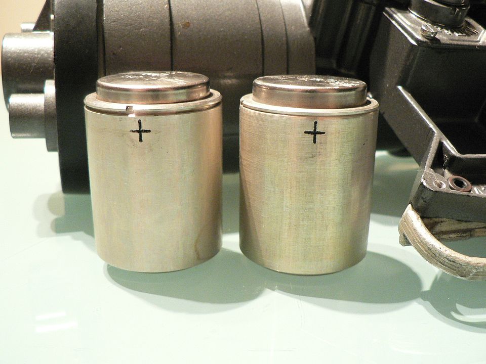
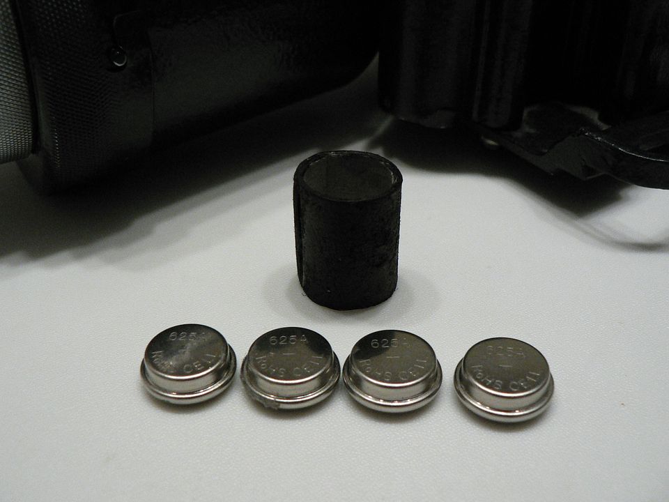
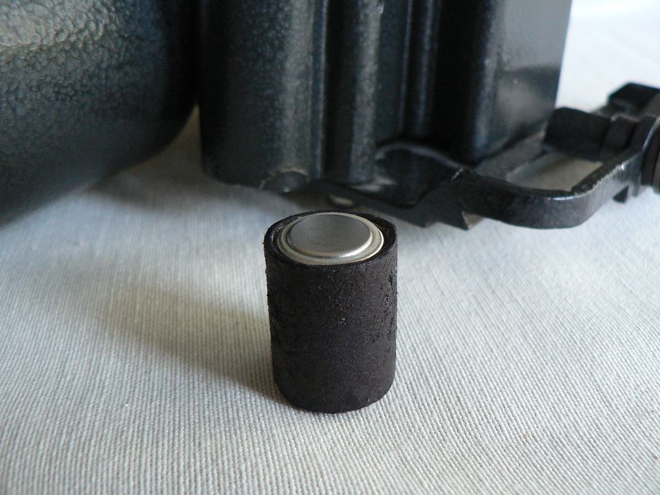
I briefly touched upon it earlier but I want to elaborate.   The nominal voltage supplied by the battery pack is 5V.  The internal electronics then bump the voltage up to the 19kv (that's 19,000 volts!) required for the intensifier tube to operate.  That amount of charge doesn't just magically dissipate instantaneously when you turn the power off.  It takes time for the tube to power down.  How much time?  I can't tell you exactly but it's a number of minutes.  What that means is, even though the power is switched off, the charged tube is still sensitive to light.  So, let's say you are using the scope on a sunny day.  You close the iris completely and switch it off.  About 5 minutes later, someone walks up to you and asks what the hell is this thing is you're using that doesn't even have a lens on the front.  You say "sure it does, let me show you" as you remove the filter to expose the objective lens.  You just fried your tube brother because it's still holding a charge and light sensitive.  

My advice is this.  After switching the power off, wait AT LEAST 30 minutes before removing the light filter.  Better yet, NEVER remove the filter unless you have a good and legitimate reason to do so.  That's probably overkill but better safe than sorry.  Moving on.


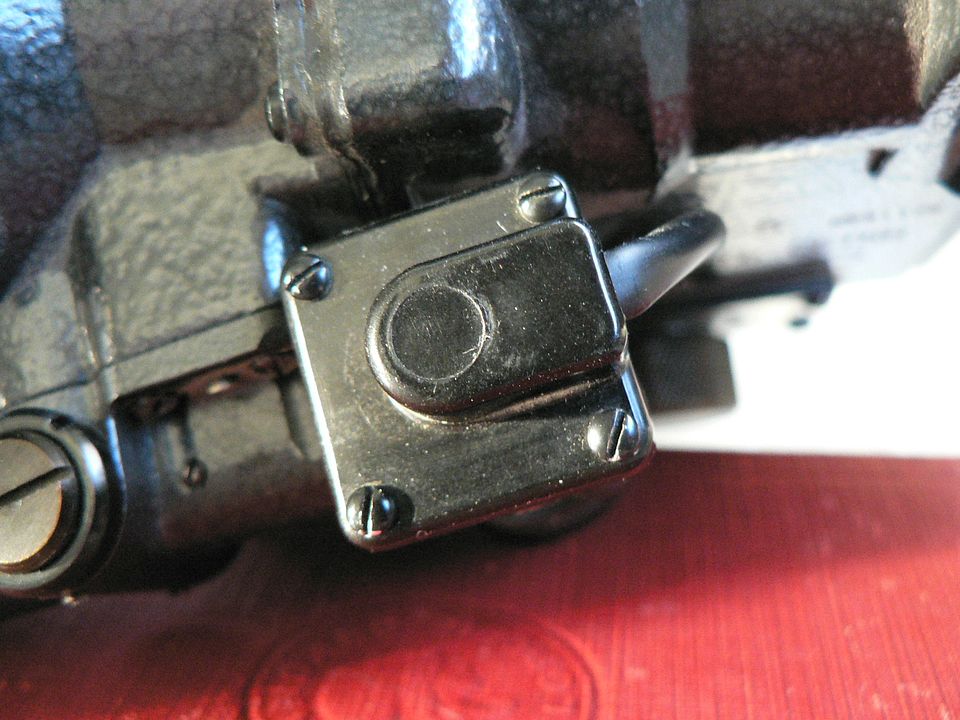
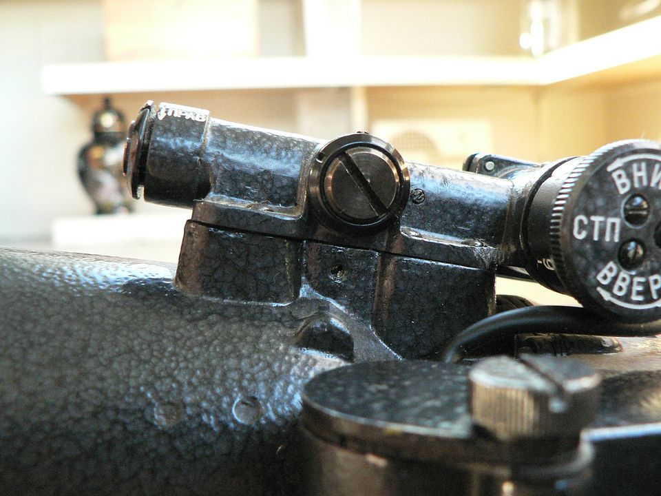
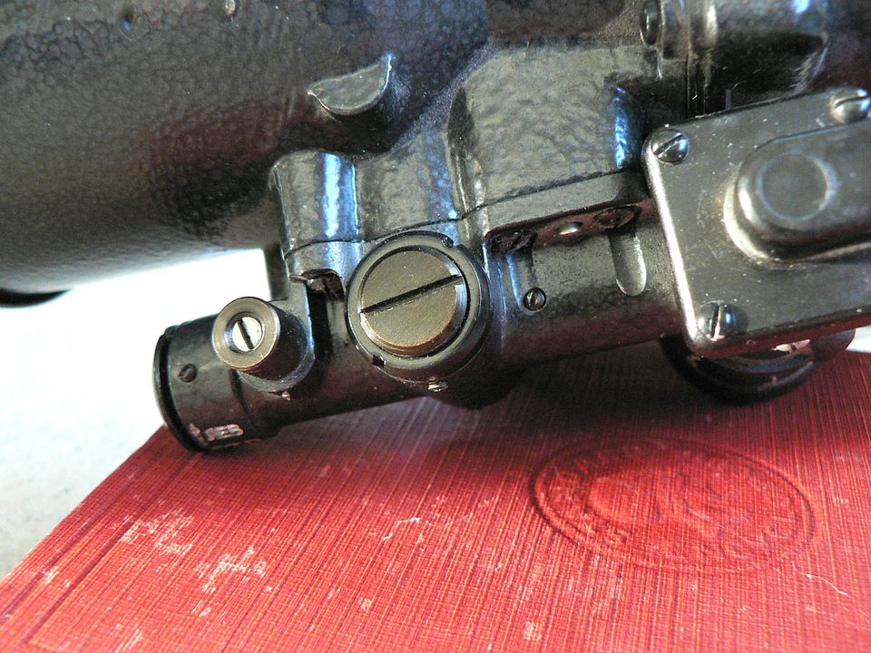
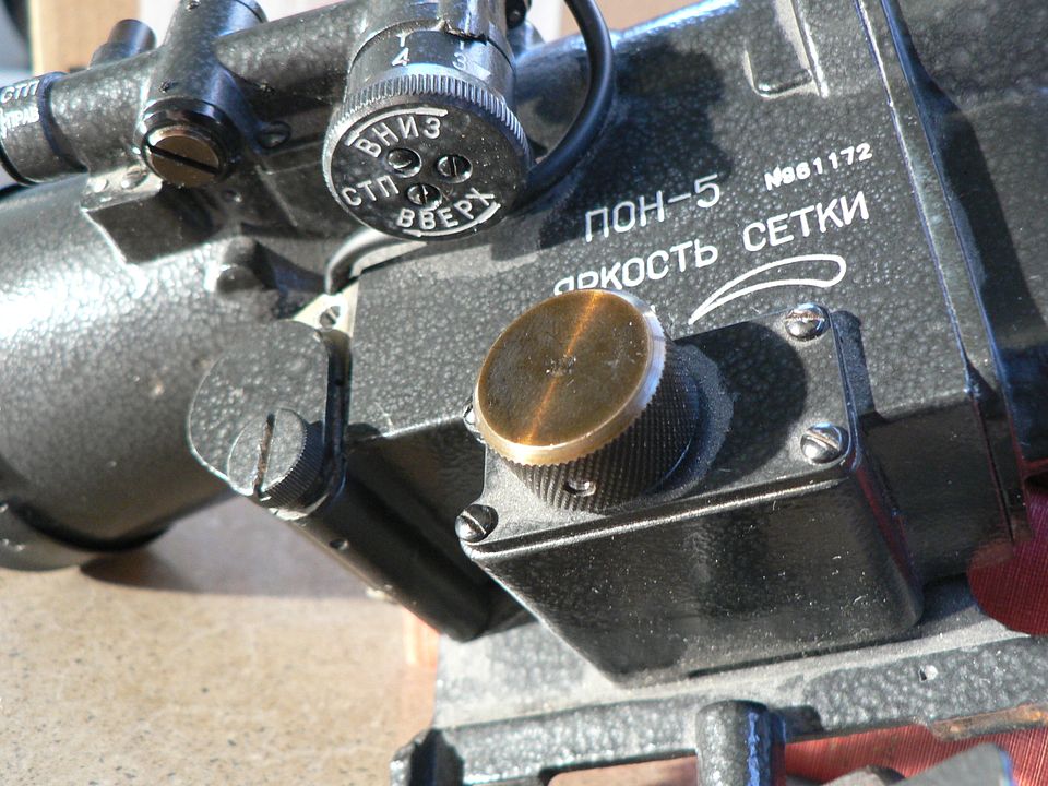
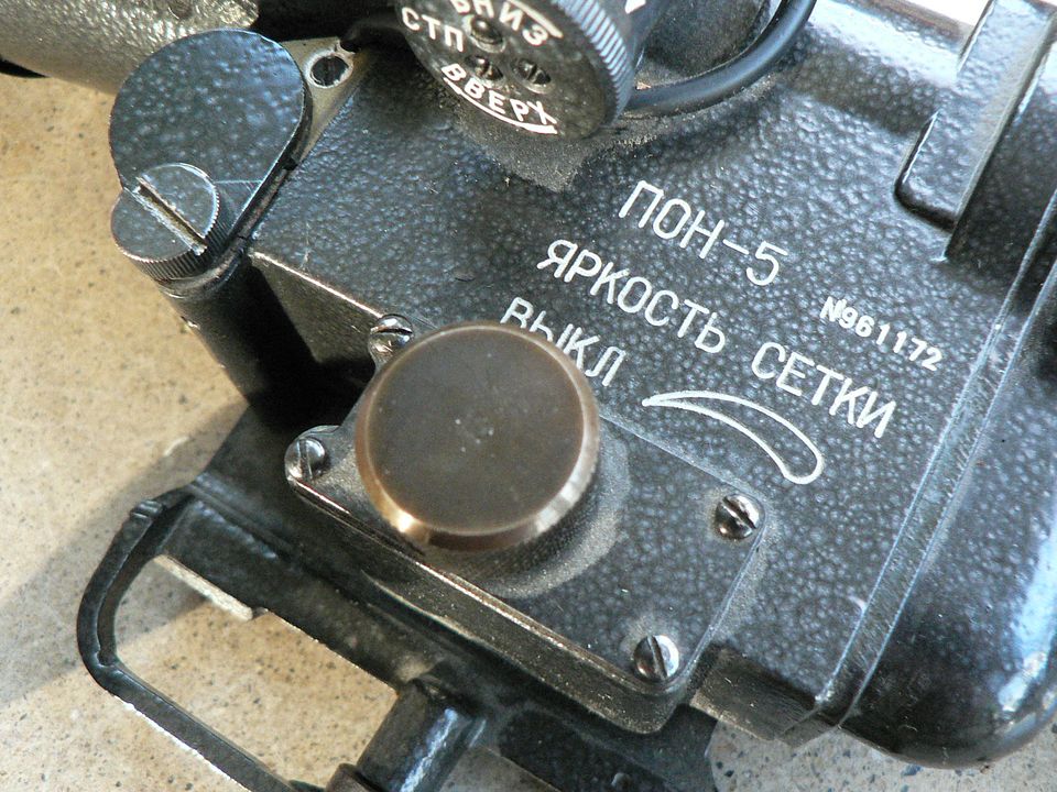
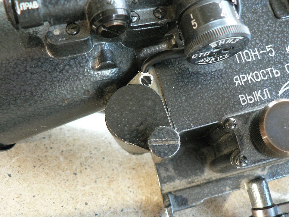
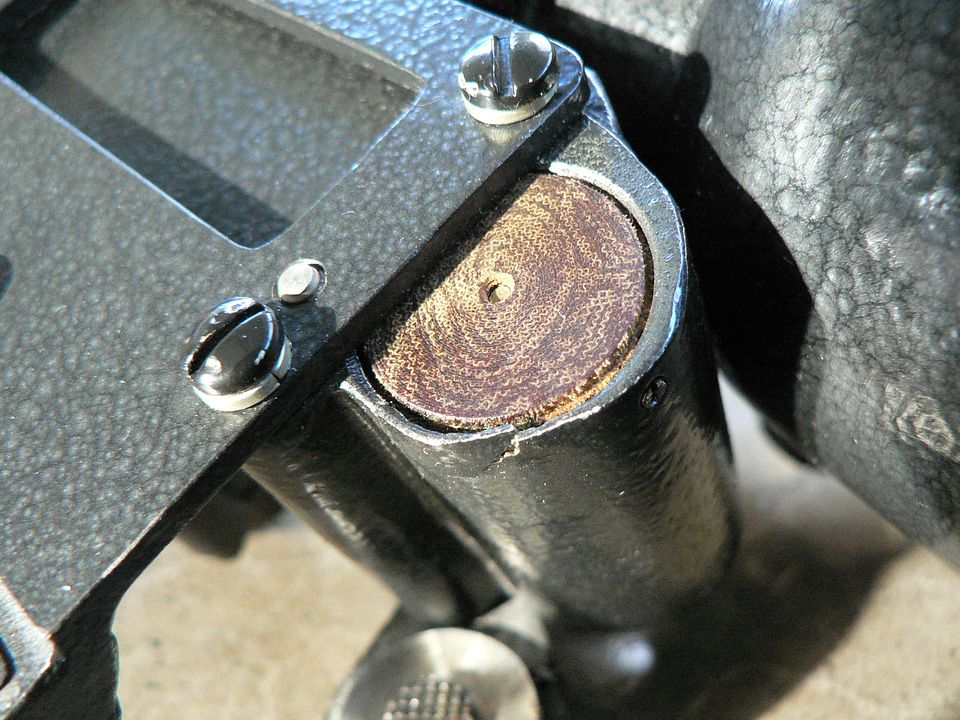
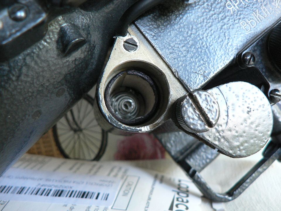
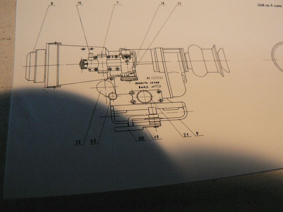
The objective lens you see in the picture above is just the first of a number of lenses contained in the front lens block.  This block is then attached to the main body of the scope using four slotted screws. Two of those screws are visible here, on the right side:


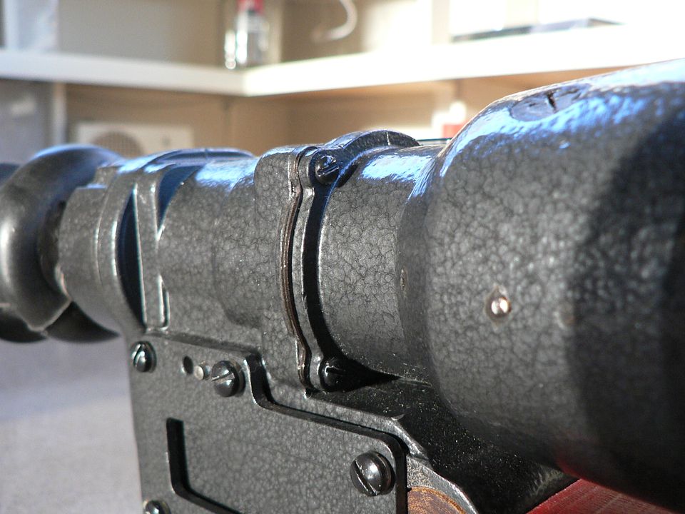
The other two are on the left side.  Notice that there is a gasket in place between the front lens block and the main body.


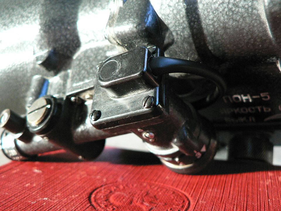
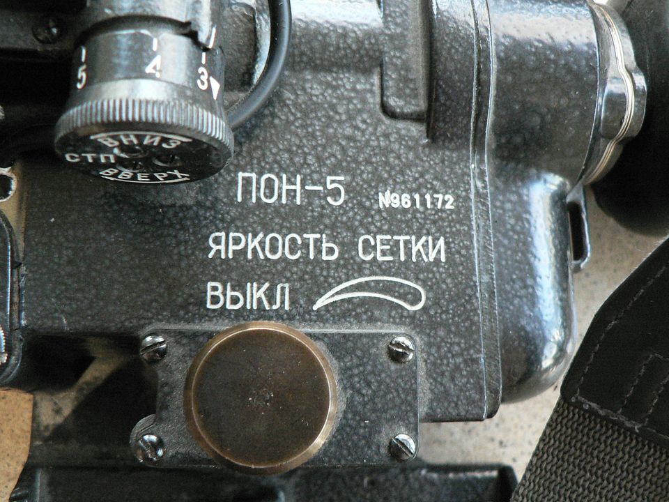
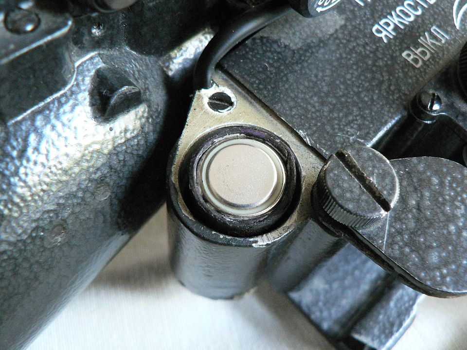
There are numerous other screws found on the body of the front lens block, several of which are shown in this picture:


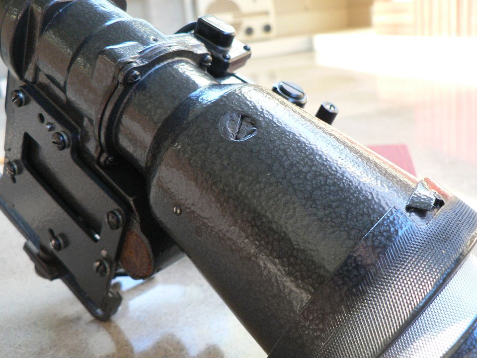
The large screw appears to have some funk smeared on it.  This is a rubbery covering intended, I assume, to act as a waterproofing agent.  There are two smaller screws below the larger one but one of the two is barely visible because of the same coating.  As I said, there are others as well.  Just underneath the large screw is an internal ring holding a number of lenses.  My guess is that this screw is used to mount them in place.  The various other small screws are most likely used to properly align the internal lenses during manufacture.   They probably also serve as stop pins to hold everything fast in place if the unit takes an impact.  


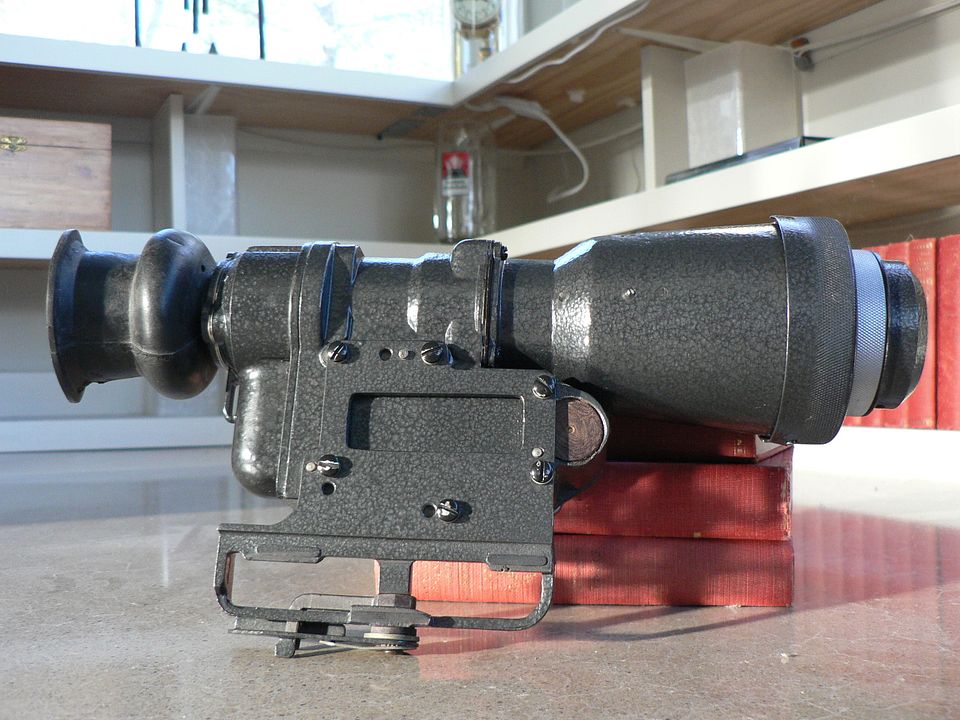
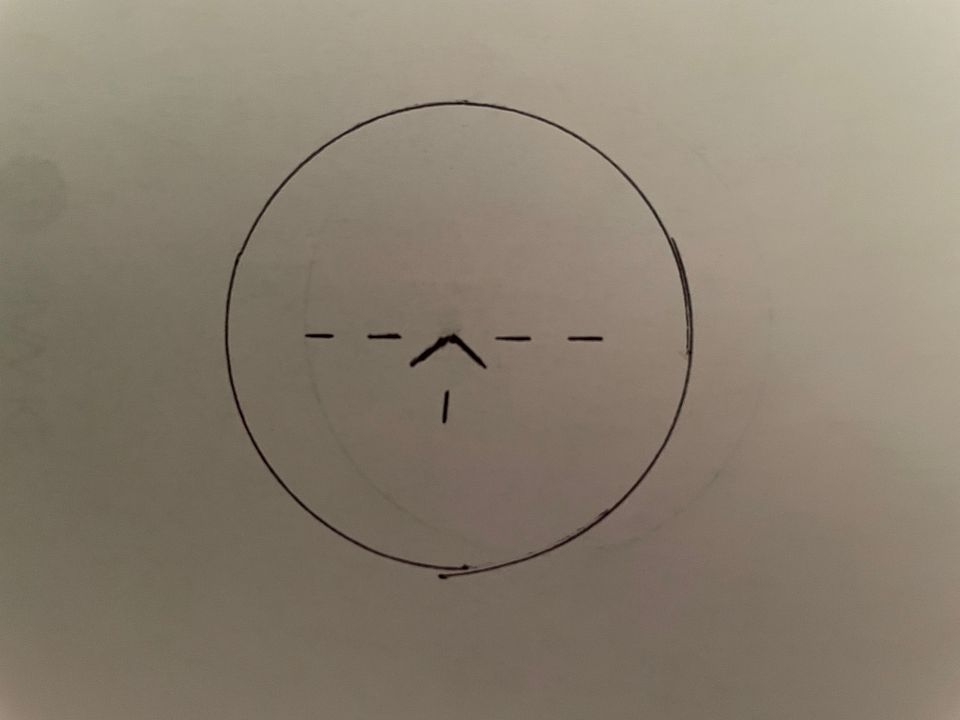
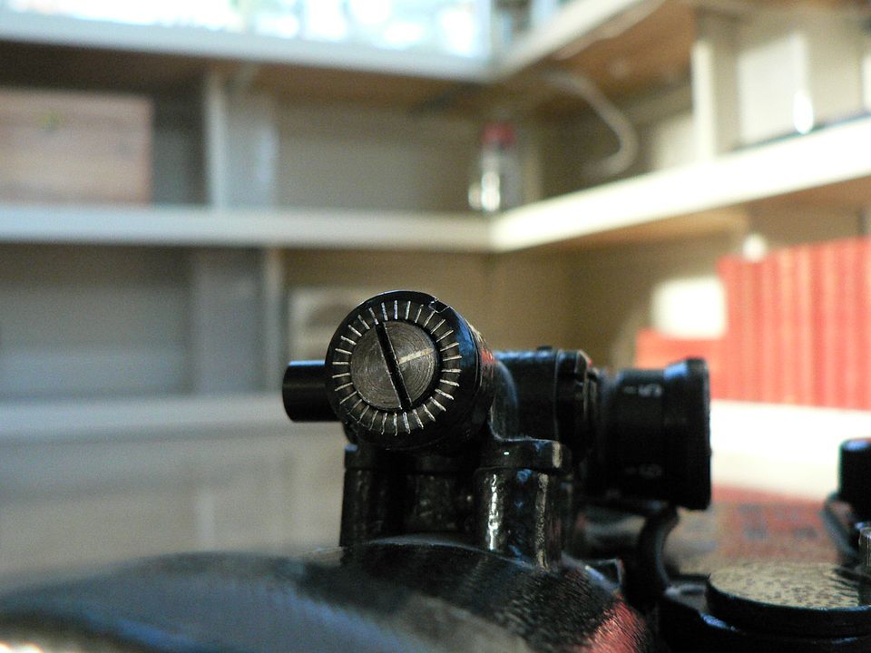
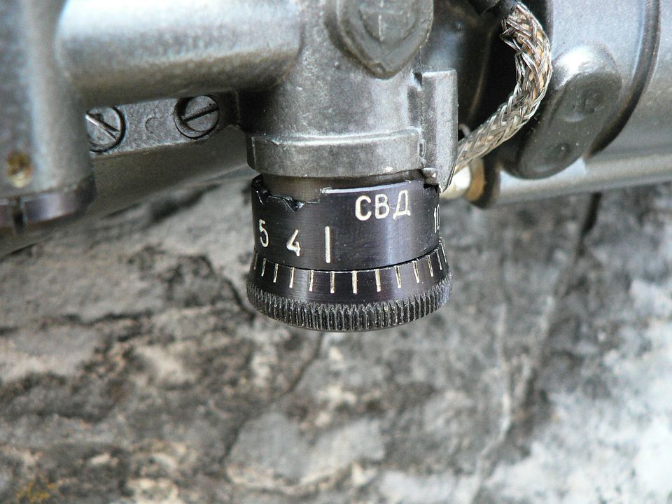
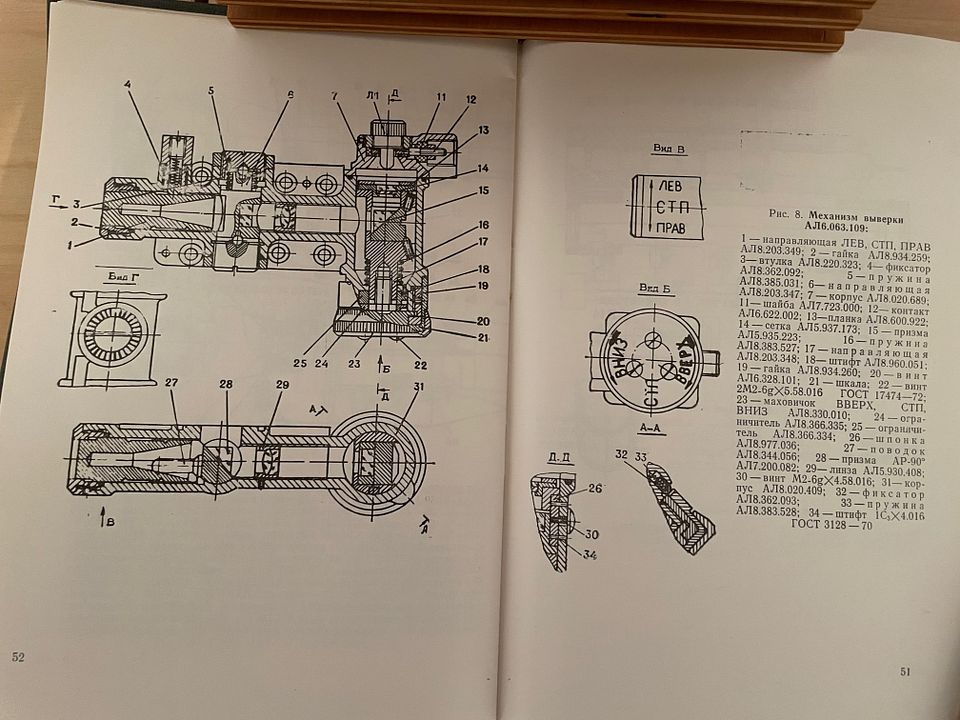
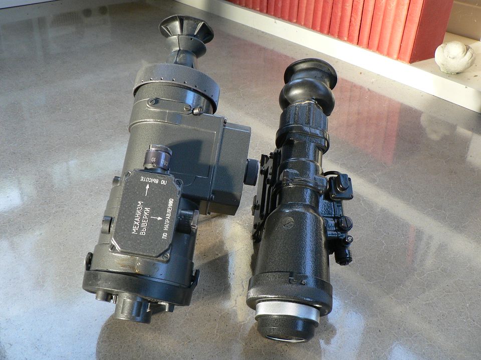
Mounted on the left side of the front lens block is the, to quote the manual, "alignment mechanism".  It's used to adjust the windage and elevation.  It also houses the reticle and reticle light.  We'll cover that in the next post.
Link Posted: 3/9/2023 12:56:07 AM EDT
[#2]
Alrighty, it's time to look at the "alignment mechanism".  Generally speaking, most older Soviet/Russian NV designs use a standard windage/elevation mechanism that, while not actually interchangeable between the various scopes, is identical in function, adjustment, and use.  All contain a glass plate inscribed with a reticle lit from above by either an incandescent bulb (older units) or an LED (newer units).  All have a range drum hanging from the bottom that features a replaceable ballistic cam so that the scope can be used on a wide variety of small arms and all are windage adjustable using a screw at the front.  As an example, we see below the alignment mechanisms on the PON-5 and a 1992 dated 1pn58:


While they are not interchangeable between the two units, they are functionally identical.


So, how do they work?  We'll start with the light source.  Mounted at the top rear of the mechanism is a plastic cover secured by four screws:


Underneath this cover is the light source for the glass reticle plate.  Although I am not certain, I believe it's an LED on the PON-5 but I'm not taking this cover off to find out.  I know it's an LED on the 1pn58 because that bulb simply screws in place so as to be easily replaceable in the field without the need to remove a cover.  


Coming out the back of the plastic cover is an electrical wire for the lamp that goes down and disappears into the body of the scope:


The reticle lamp is controlled by a rheostat knob on the body of the scope which we'll look at later.  In this way, the user can control how bright the reticle image is ranging from no reticle to super bright.  This is necessary because the general image brightness varies depending on ambient light so the reticle could be washed out in some instances necessitating the need for brightness adjustment.  You might be wondering why the reticle is not simply at constant maximum intensity.  There are two reasons for this.  First, an extremely bright reticle imposed on a dimly lit image results in unwanted blooming of the reticle.  Second, too much reticle intensity is damaging to the intensifier tube.  So, it is very important that the reticle intensity be adjusted so that it is just bright enough to be useful, no more.  


?Usually, I can get a good, clear picture of an actual reticle but I was unable to in this instance so, with apologies, I can only provide a crudely done by me drawing of what the reticle on the PON-5 looks like:


Normally, there is a drawing in the manual showing the reticle and various measurements so that it can be used for rudimentary range finding but, as this particular unit is a commercial model, the included manual is, to put it politely, a little lacking on detailed information.  What I can tell you is that this reticle is rather basic compared to those used in some other Soviet NV scopes which is a clue that this was intended as more of a low light aiming sight rather than a long range use scope.  I'll have more thoughts on that in a bit.  Also, I should point out that the reticle is not optically centered in the image.  In other words, you can actually see the reticle move left/right and up/down in the image when you are adjusting windage and elevation.  


Now, let's go back to a side view of the adjustment mechanism and I'll explain how the reticle is made visible in the image when your peeper is looking into the ocular lens:


Referring to the PON-5 alignment mechanism in the photo, the bulb is lit at the top rear of the mechanism.  This shines down through the glass reticle plate which is internally mounted just above where you see the silver colored pin in the body of the mechanism, projecting an image of the reticle into a prism mounted behind the small, silver, slotted screw.  This prism turns the image 90 degrees towards the front of the mechanism and projects it forward until it encounters another prism mounted in the vertical tube you see located at the approximate midpoint of the mechanism.  There, the image is turned 90 degrees to the side and projected into the objective lens block where it encounters yet another prism which again turns it 90 degrees into the viewer's line of sight.  Get it?  I hope so because that's about the best I can explain it.


There is a large, slotted screw on the bottom of the vertical cylinder at the midpoint of the mechanism:


And another at the top of that cylinder:


NEVER, EVER mess with these screws.  They were put in place at the factory after one of the reticle projection prisms was installed in the cylinder and adjusted.  Just LEAVE THEM ALONE.  Forward of the large screw on top of the mechanism is another smaller, slotted screw.  This has to do with the windage mechanism.  However, it's not an adjustment screw but rather part of the assembly process and should also be left forever undisturbed.


So, that's the reticle.  Next post, we'll see how windage and elevation are adjusted.
Link Posted: 3/13/2023 2:17:46 PM EDT
[#3]
Now it's time to see how we adjust windage and elevation and we'll also discuss the "ballistic cam".  


We start with windage.  This is adjusted using a screw at the extreme front of the alignment mechanism:


This screw is not click adjustable. In other words, it doesn't "click" from position to position.  Rather, it simply turns just like a regular screw only there is some drag on it so that it stays where you put it.  These is an index mark on the screw itself that you line up with one the marks on the body of the mechanism.  Each mark is .5 MOA which translates to approximately .5235" at 100 yards for us Americans .  When viewed from the front, turning the adjustment screw clockwise moves the reticle to the left which moves the point of impact to the right.  Conversely, turning the screw counterclockwise moves the reticle to the right and the POI to the left.


As we turn the scope to look at the left side of the mechanism, we see the windage adjustment indicators in Russian:


The top marking is "LEFT", the bottom is "Right", and the letters in the middle stand for "Mean Sighting Point" a.k.a. Point of Impact.  Again, the reticle is not optically centered.  This means you can actually see the reticle moving right or left in your field of view as you turn the adjustment screw.  That's it for windage; easy-peasy.  


Now for elevation.  It's almost as simple but the addition of interchangeable ballistic cams changes it up a bit.

At the bottom rear of the alignment mechanism is the elevation knob, seen here at it's lowest range setting of 300 meters:


I have to apologize here because there is glare in the photograph partially obscuring an index mark on the body of the mechanism.  It'll be more visible in later pictures.  There is a built in stop which prevents turning it below the "3" setting.  Just to the right of the "3" is a white triangle.  This mark is used for zeroing the elevation and it normally points to index marks on the splined knob.  However, for reasons unknown to me, there are no such marks.  Perhaps it's because this is a commercial unit?  I simply don't know.  

For comparison, here is the equivalent arrangement on a 1pn58 showing the index marks absent on the PON-5:


Confused yet?  Don't be.  It'll all make sense when we get to adjustment in a little bit.


?For now though, let's assume the scope is properly zeroed and look at the earlier picture again:


So, the range setting is "3" or three hundred meters.  If the target is closer, you'll just have to use some good 'ol kentucky windage.  You have to remember that this was originally designed for combat use so, as long as you are aiming center mass at a man-sized target, you will get a hit at anything up to 300 meters distant when using this range setting.


?Turning the knob clockwise (when viewed from beneath) it will "click" to the "4" for a target 400 meters distant:


Now we don't have as much glare and we can see the index mark on the knob lined up with a corresponding mark on the mechanism body.


Continuing on, we have a setting for 500 meters:


600 meters:


And, finally, 700 meters:


There is a built in stop which prevents turning the knob beyond the "7" setting.  


Up to this point, I've been referring to "turning the knob" which is exactly what you are doing.  However, the range numbers are not painted on the knob itself but rather on a separate sleeve fitted over the knob and known as the "ballistic cam".  This cam can be removed and replaced with a different cam when the sight is used on a different rifle which may or may not be of a different caliber.  In this way, the same sight can be used on a whole host of small arms simply by switching out the ballistic cam.  Normally each cam is marked with the weapon it's designed for but there is no marking on the one fitted on this PON-5, presumably because they didn't expect the end user to own a host of different things to fit it on.  In this case, the cam fitted is calibrated for 7.62x39.  

?To illustrate what I'm talking about, here are the ballistic cams that were included with my 1pn58:


On the far left is on marked "AKM" rifle.  Even though it's not marked, that's the one currently installed on the PON-5.  Moving to the right, we have the AK74 rifle(5.45x39), RPK light MG(7.62x39), RPK74 light MG(5.45x39), PK general purpose MG (7.62x54), and RPG-7 anti-tank rocket launcher.  Not seen is one for the SVD (7.62x54) because it's currently fitted to the 1pn58.  At the extreme right is the plastic case for the various cams.  So, installing any one of these on the PON-5 would enable it's accurate use on any of the above weapons.  


?No matter which ballistic cam is fitted to the unit, zeroing is accomplished the same way.  For that, we need to look at the bottom of the knob:


We start with the three screws in the center of the knob.  If we were fitting a different cam, we would remove all three, pull the knob off it's axle, slide the existing cam off the axle, install a different cam, replace the knob and then replace the screws.  If we are simply zeroing the scope, we would loosen the screws but not remove them.  This allows the knob to turn while the ballistic cam remains at whatever range setting you have it set to.  In practice, this would be the minimum range setting on the cam.  We then fire at a target of that distance and adjust the knob accordingly while ensuring that the cam remains at the set distance.  Turning the knob clockwise or "UP", moves the reticle down and the POI up.  Turning the knob counterclockwise or "Down" moves the reticle up and the POI down.  Normally, we would have many index marks on the knob to compare against the single index mark on the cam so that we can see just how much we've turned the knob.  But, as we discussed earlier, those marks are absent from this example, so you'll just have to put some pencil marks on the knob and wing it.  Once you have the elevation zeroed, tighten the screws and you're done.  DON'T GO GORILLA OR YOU'LL STRIP THEM!!


So, that's the "alignment mechanism".  It looks complicated but, as we've seen, it's actually pretty straight forward in use once you understand how to use it.  However, I strongly recommend that you DO NOT mess with this thing other than what we've covered here.  Internally, it actually IS quite complicated and finely made (by Russian standards anyway).  To give you some idea of just how much stuff is rammed in there, here is a phantom drawing of it from the 1pn58 manual:


There are multiple prisms in there and a bunch of tiny bits.  As you turn the windage and elevation adjustments, these prisms are minutely rotated in their mounts.  These things were precision mounted at the factory and to disassemble this thing is, to be blunt, simply beyond the technical knowledge of your typical idiot such as myself.  Chances are, you're just as numbskulled as I am so do yourself a favor and don't let your curiosity get the best of you or you're most likely going to break the thing.  


In the next post, we'll look at the main body of the scope and discuss the power switch, reticle brightness adjustment, the battery box, and whatever esle catches my interest.  See you then!
Link Posted: 3/19/2023 3:05:28 PM EDT
[#4]
Very cool to see, thanks for sharing!
Link Posted: 3/23/2023 4:25:21 PM EDT
[#5]
Wait, you got Oksana's phone number in addition to getting the scope?

It's a very cool device, I wish I could see what the picture is like in the dark.
Link Posted: 4/19/2023 9:45:12 PM EDT
[#6]
It's been a while since I've had a chance to work on this.  Part of the reason is technical (computer died) and part of it is situational (it's spring) BUT I'm back and it's time to get back on it.  We're not far from finished sooooooo, here we go.......


Next up is the main body of the PON-5.  It's the main "chassis" of the unit and it's made, as is much of the unit save the clamp that holds the unit to the rail on the rifle and a few smalll bits, out of a nonferrous alloy.   It houses the intensifier tube with its supporting electronics, the power switch, batteries, and acts as a mounting point for the front lens block, rear cover and rail clamp.  Here are the markings on the body:

At the upper left, we see the serial number (N961172) with "96" indicating the year of manufacture.  To the left of the serial number is, obviously, "PON-5" in Russian.   The second line translates to "RETICLE BRIGHTNESS" and the third, "OFF", meaning that the unit id switched off when the control knob turned fully to the left.  The strange looking shape after "OFF" is a graphic indicating that the farther the knob is turned to the right, the brighter the reticle becomes.


Here's a closer look at the control knob:

It has a gold/bronze hue and is made of some type of metal.  It clicks as you turn it so that it stays on the setting you've set it to and it turns through an arc of approximately 90 degrees.  It's important to understand, the intensifier tube itself is either simply "ON" or "OFF". So, turning the control knob one click to the right powers the unit on.  At this setting, you will be able to "see" with the scope but you will not see a reticle.  Essentially, you are only using the scope for nothing more than observation at this setting.  As you turn the knob progressively to the right, click by click, the reticle will start to faintly appear and become brighter and brighter with each click.  You only turn the knob far enough to clearly see the reticle, no more.  The brighter the ambient light, the brighter the reticle will need to be.  If you are in a relatively bright setting but move to a darker one, you will need to adjust the brightness of the reticle accordingly.  Always remember, from the first time you power up the intensifier tube, you begin reducing it's service life.  The more light you introduce into the intensifier tube, the less service life it retains and reticle brightness contributes to its eventual demise.  So, never turn the reticle up higher than you need for the task at hand.


Notice the control knob it's mounted to a plate held on by four small screws:

Removing these screws will allow access to power switch which is, I assume, not much more than a rheostat.  No, we're not taking that apart!


If you needed to service the electronics package/intensifier tube, you would gain access by removing the rear cover, shown below in a left rear oblique view:

It's fastened to the main body by six screws, three of which are visible in the photo above.


Mounted to the right side of the main body by six screws is the steel bracket used to mount the scope to the rifle:

This bracket can be switched out with other brackets allowing the scope to be mounted on other weapons systems.


Here's the bracket as seen from the left side:

This is a typical combloc mounting setup utilizing a cam on the axle that locks into a cut in the rail to more securely holt it in place.


A detail view showing the locking lever rotated to the rear or "locked" position:

Because this is a standard combloc mounting bracket, I'm not going into the details of how this it works.  I'm assuming that anyone who has read this far already knows.  If not, well, get to doing a little research!


Molded into the main body and found at the front of it below the front lens block is the battery compartment.  It's accessed from the left side of the scope and is shown here with it's cover secured in place by a non-removeable slotted screw:

The screw head is splined to as to be easily tightened by your fingers.  It should NEVER be tightened with a screwdriver.


Here, we have loosened the screw and swung the cover out of the way allowing a view into the battery compartment:

Four button cell batteries are used in a stack (4x1.35V Type RTs-53).  We'll go into more detail on that later because it's complicated.
Link Posted: 4/19/2023 10:05:02 PM EDT
[#7]
Detail showing the loosened battery compartment cover screw (notice gripping splines) and a spring that keeps tension on everything when the battery stack is installed and the cover tightened down:


Back side of the cover showing the checkered electrical contact point:


Notice the cracked rubber seal.   YaY superior quality Russian materials!!


If we flip the scope over and look at the right side of the battery compartment, we see that it's actually hollow all the way through with a resin-fiber, nonconductive plug installed:


?Now, is this sophisticated technology or what??  Hey, if it works.....
Link Posted: 4/19/2023 10:49:28 PM EDT
[#8]
The last thing we need to look at on the scope proper is the rear lens group and rubber eyecup:


Pretty isn't it?  The rear lens block is held to the main body rear cover by three screws.  Notice the metal "gasket".  it looks to actually be a number of thin layers stacked on top of each other creating a laminated appearance.  I'm not certain but this "gasket" may actually be a number of thin shims used to adjust the focal distance of the rear lens block relative to the intensifier tube.  Agian, this is only an assumption.  I have no proof of that.   As for the rubber eyecup, it's a bit malformed from sitting in the storage bag for an extended period of time.  That's ok....it still works.  The rubber is held onto the ocular lens by simply stretching it over the lens until a lug molded into the eyecup snaps into a groove machined into the lens block.  It's showing some slight degradation but is still plenty flexible and 100% useable.  I'm sure it'll last for a long time to come but it shouldn't be kept in the storage bag smashed in as it has been for years.  Better to either stop using the bag or remove the eyecup and store it separately when not in use.  


Here, it has been removed and we are looking at the rear of the eyecup:


I've positioned it so that light is coming through a small hole at the front.  There are two of these and their purpose is to allow for the egress and ingress of air when you put the thing up to or remove it from your face.  Without these holes, you might end up suctioning the scope to your eye socket.  That would not be good!


The front of the eyecup showing the lug that snaps onto the rear lens block:


Looking at it from this angle, we can clearly see the two vent holes I mentioned above.


Finally, here we are looking straight on at the ocular lens with the eyecup removed:


The three mounting screws are clearly visible and thy have some of the rubbery gunk seen earlier on the front lens block, the purpose of which is to waterproof the unit.  

If you're not familiar with night vision optics, you may not know that you don not "look through the unit as you would a normal scope.  Rather, when you look into the ocular lens, you are looking at a "screen" which is made to glow depending on the number and velocity of electrons shot at it out the back of the intensifier tube, thus creating a greenish image that is useable to the human eye.  The number and velocity of the electrons shooting out the back of the intensifier tube is directly proportional to the number of photons entering the front of the tube through the objective lens.  The "intensifier tube" is called that because, for every photon that enters the front of it, a much larger number of electrons exits the back.  Thus it, amplifies few multiwavelength photons into many electrons and then, by way of the little screen you see through the ocular lens, back into photons in a wavelength visible to the naked eye?  Make sense?  Don't feel like a boob if you don't get it.  Truth be told, there is a LOT of math and science that goes into the entire process and I don't get all of it either.  Obviously, it works though!  


So, that's it for the scope itself.  In the next post, I'll tell you a little bit of what I've surmised about its intended role through my limited experience with it.  However, I've never read any official Russian documents detailing exactly what they were trying to achieve with this thing so take my musings for what you think they are worth.  After that, I'm going to post every single page in the commercial manual that is numbered to this unit and give you my thoughts on batteries.  Okiedokie Smokey.  Peace out and we'll meet back here shortly.  I promise you it won't be so long this time before the next post.
Link Posted: 5/3/2023 12:02:00 AM EDT
[#9]
Alrighty. We've looked at the PON-5 in detail. I've gone over all the little bits that matter and I've explained how to make adjustments, cautions in use, and what to just leave alone. Now I want to discuss what I believe the intended purpose of this thing was.


Basically, I believe it was meant to be used as a small but effective optic to be used in an urban environment at night. I think they wanted it to be small, light, and rugged but there were limitations as to what could be achieved cost effectively in the Soviet Union/Russia at the time.


Let me explain. Without question, this is a Gen 1 unit and it only contains one intensifier tube. For comparison, here we see it alongside the 1pn58 manufactured in 1993, another Gen 1 unit, it was manufactured three years before the PON-5:


Notice how much longer the 1pn58 is. That's because it has three intensifier tubes lined end to end. The net effect of doing this is a unit that is useable in all but a pitch black night. The drawback to this is twofold. First, it's a heavy and unwieldly thin, heave, long, and just plain cumbersome. Second, the three tube setup creates quite a fisheye effect, much as you would see when looking through a security peephole on a door. No, it's not nearly THAT bad but it is significant. And, while you get used to it over time, it's still there and would be a significant impairment when engaged in close in fighting. The single tube on the PON-5 eliminates the bulk and optical disadvantages of the 1pn58, but the trade off is much less light sensitivity. It's pretty much useless in a forest or countryside setting. For it to function, you need a fair degree of ambient light, levels only found in an urban setting.


Okay.....so let's just install a Gen 2 tube in the thing. We can use it in just about any light conditions. Problem solved. Welllllll, not exactly. You have to remember, we're dealing with Soviet era technology here. Their equipment was somewhat crude compared to ours. Sure, GEN 2 NV was around but it was bulky. For comparison, let's take a look at the PON-5 compared to what was then a state of the art GEN 2 unit, the 1pn51:


The 1pn51 was, by Soviet standards, an excellent unit. It's much more user friendly than the 1pn58 it replaced, has better built in safeties, a worlds better image with no fish eye, and it has a diopter adjustment ring, something, to my knowledge, unknown on any of the earlier Soviet NV equipment. At first glance, the side-by-side comparison is favorable between the two.


However, a top view shows the 1pn51 to be substantially wider than the PON-5. It's also significantly heavier, 2.10 kg compared to the PON-5's 1.3 kg:


Most telling of all is the front view:


The 1pn51 is actually quite the fatty! So, although shorter than the 1pn58, the 1pn51 is still a bulky and heavy unit.


So, in my opinion, the PON-5 was a compromise optic, designed to be light and compact (by Soviet NV standards of the day). The tradeoff was that it could only be used in area of relatively high ambient light.


One more post and we're finished. Next time, we'll look at the manual and I'll show you my solution to the battery problem. If you have one of these units, you know what I'm talking about already and my hope is that I can show you how to get your old scope back to the range.  See you then.
Link Posted: 5/4/2023 7:02:02 PM EDT
[#10]
Someone on another forum brought it to my attention that it would be nice to see what it looks like when actually mounted to a rifle; something that should have occurred to me from day one.  Thay don't call me Moe Ron for nothing!!  So, I managed to round up a Romanian SAR-2 to mount it on for a few pictures; one last detour before covering the manual and batteries.


First up is a general side view to give you some idea of size:


And a 3/4 front view:


When viewed from the front, we can see that no attempt was made to center it over the rifle.  In fact, it's very much biased left:


A rear view illustrates just how far left it really is.  I found it easiest to use my left eye when aiming right-handed:


And finally, a top view:


You could probably disassemble the rifle for cleaning while leaving the scope in place!
Link Posted: 5/4/2023 10:38:26 PM EDT
[#11]
The last item I want to discuss is the manual.  I thought this was only going to take one post but I've realized just how many pictures that's going to be so it's actually going to take more than one because you can only post so many pictures at a time.  Anywho, some background first.


First off, I don't speak Russian and I sure as hecks don't read it.  Because of this fact, translation is excruciatingly slow.  To properly translate technical Russian text, you first have to bring up a Russian keyboard and type it in strange, unfamiliar character by strange, unfamiliar character before sending each sentence or small group of sentences through a bot translator, and characters sometimes change from lower case to capital.  Then, you have to decipher exactly what the true meaning of the translation is and essentially reform it into a useable English form.  Compounding the problem is the fact that some of their lower case letters look like our upper case letters so you sometimes don't know whether what you are looking at is in all caps.  If it is, and you don't realize it, you end up with all sorts of wonky stuff when you then send what you've typed to the bot translator.  If that happens, you simply have to start over.  Also, a different Russian font than the one you are using on your virtual keyboard can change the looks of some characters into something unrecognizable compared to the font you happen to be using.  Still, although laborious and perplexing, it can be done.  You just sort of have to approach it like you're deciphering an alien language.  Add in the fact that I work two jobs, I'm currently working on other translation projects for various French firearms,  work around the house, life in general, spring time projects, motorcycle refurbishment.......well, you get the idea.  So, I translated enough of the manual to get done what I needed to get done. I'm providing the rest to you in picture form and providing most of the section headings so that you can decide what you are interested in and translate in your own time.  The paper it's printed on is cheap and the ink used was subpar so some of it may not have been picked up so well by the camera but, hey, what I'm providing is better than nothing.  You CAN figure it out, but you just have to want it.  


We begin with the cover:


?Roughly, "Optical night sight PON-5 Passport Manual BSh 3.812.151.  PS


The "cover" is made by simply gluing a hand cut out piece of lined paper with typed (not printed but typed) text to a piece of cardboard and folding that cardboard in half.


A detail of the paper glued to the cover:


Inside of front cover:


The front and rear covers are a thin cardboard.  Think toilet paper roll quality only thinner.


A detail shot of the cover cardstock:


The entire manual is made as cheaply as possible.  The height of the various pages varies, almost as if they were cut by hand on a paper cutter.  For example, the tops of each page line up:


But the bottoms are a different story:


The width of each page is the same but no two pages are the same height.  It's hilarious!

The overall construction method makes me suspect the whole thing was done on one long strip of paper using an old school stencil duplicator process.  Then, it was cut up using a hand operated paper cutter to create the individual pages.  That would also explain why the back of each page is blank.


Additionally, the staples holding the whole thing together look like they were done on a machine that has been limping along since 1943:


Title page:


 AOOT = "Public Joint Stock Company"  (Thank you Maxim Popenker).  Then we have "ZOMO" Which stands for the "Zagorsk Optical Mechanical Plant".  Note the date "1995".
Link Posted: 5/4/2023 11:34:10 PM EDT
[#12]
After the title page is page 2 starting with Section 1.  USE:


Page 3 is a continuation of Section 1:


Page 4.  Section 2.  TECHNICAL SPECIFICATIONS


The first line tells you the PON-5's magnification, 3x.  


Page 5 is a continuation of Section 2:


The first line tells you the voltage supplied by the batteries, 5V.

Farther down we have the dimensions of the unit, 275 mm x 115 mm x 120 mm.

The weight, 1.3 kg.

Time sight ready for operation from the moment it is turned on, 5 seconds.

Battery life in normal conditions, a minimum of 8 hours.

At the bottom of the page, it says "Precious metals:"

                                                           Gold..................  .0175 grams of gold

                         (precious metals continues on the following page).


Now, I skipped a bunch near the top where it looks like hand writing in the text.  We're going to consider that now.  As stated, the PON-5 is designed to run on 5V.  This is achieved using a stack of four (4) 1.25v RT-53 batteries.  Below is a picture of one I pulled off the net:


Good luck with that.  If my research is correct, they are still made in small batches and are periodically offered for sale by Russian vendors on Ebay.  Even when this manual was printed, it seems Ivan knew these batteries would be hard to get outside of Russia, so they listed alternatives that could be used and manufactured by a number of manufactures.  Acceptable batteries included the PX 625, the V625X and the MP9.  Manufactures included, among some that I don't recognize, VARTA, Duracell, and Toshiba.  At the time, these various batteries were used in a number of Western produced cameras and each was 1.35V.  That would equal 5.4V.  Great!  Problem solved!  Order some batteries!!   Wellllllll, no.  It's not that simple.  Notice I typed "at the time".  That time was 28 years ago and those batteries are themselves are now as obsolete at the RT-53.  So, we have to delve into vintage camera sites and battery conversion charts; a rabbit hole in and of itself that, if you're also interested in photography, takes you far out to sea for a couple days of learning and revelations about vintage photography.  But I digress.  Long story short, a current battery that will work does exist......for the moment.  I say that because, again, we're dealing with an obsolete power source and there is an entire path of battery designations over the years leading from the PX 625 to its current replacement the 1.5 V, 625A:


I purchased a pack of ten from Amazon for less than ten bucks made by "Loopacell":


These are made in China so who knows about quality control.  The reviews I read ranged from "GREAT!!  My old camera is back in business!!"  to "Four of the ten were dead right out of the pack".  The good thing is, they are cheap and this is only going to be used as a novelty so, thumbs up, let's have at it.  Now, again, these new batteries are 1.5V each which will give the stack a total of 6V but I'm confident that you're good to go without blowing out your electronics.  The next problem is actually fitting them because the original kit for this scope came with a "cassette" that the batteries fit into thus creating "one" 5V battery that could be changed out in a jiffy so that you didn't have to fiddle with a bunch of little button batteries in combat.  If you just throw four individual batteries in the battery compartment, they're going to rattle around in there.  At best, the scope won't work.  It worst, you're going to short the thing out.....this is bad.  Not to worry.  I've figured it out and I'll present my solution when we get to pages 11 and twelve of the manual.  So, to keep from jumping forward and back in the manual and potentially creating confusion, we'll cover my solution when we get to pages 11 and 12.
Link Posted: 5/5/2023 12:12:13 AM EDT
[#13]
Page 6 finishes Section 2 and contains Section 3. NIGHT SIGHT COMPLETE KIT:


At the top, it lists the other precious metals, .5758 grams of silver and 404 grams of aluminum.

Section 3 lists a number of things not present with this particular unit.  Whether they have been lost with time (probable) or never came with it in the first place (possible) I cannot say.  I have no idea what some of the items actually are given my limited translation capabilities.  As should be obvious, parsing out the meaning of entire translated sentences is easier than figuring out random single words.  So, I'll tell you what I know and put question marks beside the things I don't know.


                               PON-5     1     Present

                                  Case      1     Present

                      Stacking box     1     ??

     "Contact" or "Hookup"     3     ??  I think these are springs to be inserted

                                                             between the individual batteries in the cassette.

                             Cassette     1     Missing.  This is for the battery stack.

                                  Latch     1     ??

                               Eyecup     1     Present

                        Screwdriver     1     Missing

                               Napkin     1     Present....I think this is the lens cloth

                              Manual     1     Present

At the bottom it says:

                Note:    It is possible to supply the sight with various types of weapons mounting brackets at the request of the consumer.


Page 7.  Section 4.  DEVICE AND PRINCIPLE OF OPERATION:


Also on this page:

    4.1  Objective lens

    4.2  High voltage converter.  


Page 8 continues Section 4:


    4.3  Control unit

    4.4  Alignment mechanism (elevation and windage)


Page 9 finishes up Subsection 4.4:


Page 10 continues Section 4:


    4.5 Diaphragm.  (the front light filter)

    4.6  Eyecup.


Next up is page 11 where we discuss the battery cassette.  But it's after midnight and I have to be up at 5:30 so this is a good stopping point.
Link Posted: 5/18/2023 12:48:04 AM EDT
[#14]
Page 11 continues Section 4:


4.7 Loading battery cassette.

This section explains how to load the "cassette" with four RT-53 batteries alternating with three contact springs which "serve to improve contact between the batteries", thus creating a single 5V battery that can be switched out as a unit when necessary.  The shape of the cassette also prevents it from being inserted into the battery compartment with polarity reversed. To change out the cassette you loosen the battery compartment cover locking screw a number of revolutions until you can swing the cover out of the way.  Then, you eject the cassette with discharged batteries, insert a fresh cassette, swing the battery compartment cover back into position, and finally, while holding the cover in place with your thumb, tighten the cover locking screw down by hand or with a screw driver.


This all sounds good and fine.  The problem is, this unit is missing its cassette and I have absolutely no idea what one looks like.  I assume it's a thin plastic shell with an opening at one end that allows the "+"  head of the first battery in the stack to protrude.  At the other end, I expect there would be a cap that screws down to compress the stack.  This cap would have a hole in it exposing the "-" side of the last battery.  In effect, you would have a miniaturized version of the battery cassette (with plastic body instead of a metal alloy) used in both the 1pn58 and 1pn51 scopes.  That battery is shown below:


Ok.  So we have no cassette.  Are we screwed?  No.  We make something that approximates one.  We have to have one.  You can't just stick four batteries in the battery compartment and close the lid for two reasons.  First, they will rattle around in there.  The compartment is designed to accommodate a plastic cassette surrounding the stack of batteries.  Without that cover to take up space, the stack is unstable and can move around under shock, i.e. recoil.  Second, there is no nonconductive lining in the battery compartment; the sides are of the same metal alloy as the rest of the scope body.  This means that the batteries rattling around in there will cause an electrical short.  The reason they got away with a metal cassette on the batteries shown above is that they are lined with a nonconductive sleeve.  So, we HAVE to have a nonconductive sheath around the battery stack to both prevent rattling and electrical short.  What to do?


Well, the obvious solution is a plastic sleeve.  It can be open at both ends because we aren't taking this thing into combat.  We can load the batteries into it one by one, no problem.  Where we run into difficulty is finding a plastic sleeve with both a proper inside diameter to fit the batteries snugly AND a proper wall thickness to fit the battery compartment properly.  Length is unimportant as we can always trim it to size.  I guarantee you such a thing exists but it's something you are going to have to run into by accident.  In the meantime, we have to make our own sleeve and I found the perfect interim solution.  Let me explain.


The first thing you need to do is head on down to your local Post Office and ask them for one of the cardboard backers enclosed in every pack of sheet stamps.  These are throw away items to the post office so I have no doubt a window clerk will provide you with one if you are on good terms, which you SHOULD be!  It turns out, this cardboard backer is the perfect thickness for your home made cassette.  When you get home, use a sharp knife and a straight edge to cut a strip from the cardboard about 1 1/8" x 4 1/4".  Dampen (not wet but damp) the cardboard with a little water and then cover ONE side of the cardboard with elmer's glue (I used elmer's wood glue).  Wrap this tightly around a stack of four (4) 625A batteries and hold it until the glue will hold the wrap on its own.  Next, set a hair dryer on medium heat (NOT HIGH!) and blow dry the assembly until it's thoroughly dry.  The glue will give the tube more rigidity.  Remove the batteries and reinsert them to make sure they are a snug fit.  Then, with fine (250) grit sandpaper, sand the tube until the overlapped portion of cardboard is smoothed into the rest of the body and test fit into the battery compartment.  If it's a little tight, sand a little more until it's a proper fit.  It's best to sand with the batteries in place to keep the tube from possible crushing.  I then colored mine with a black magic marker to seal it a bit and give it a slightly less bubba built appearance.


If you used care, you will end up with this:


?


Here, we see our home made cassette installed in the battery compartment sans batteries:


I've found it easiest to insert the batteries into the sleeve first and then insert the assembly into the battery compartment POSITIVE  ("+") SIDE DOWN:  


If you've built your sleeve properly, the batteries will be a snug enough fit that they won't fall out while you are doing this.  Then, simply rotate the battery compartment cover in place and, while hold it down with your thumb, hand tighten the locking screw until it's snug.  Done.    Now, is this a perfect solution?  No.  It can be a little fidgety to change the batteries and you'll find that you have to tap the scope body a bit with your finger to get the batteries out.  Sometimes, when removing the battery stack, one or more of the batteries will fall out leaving the sleeve in the compartment.  Then you have to stick your little finger in there and fish the rest out.  No, it's not "combat ready" but it works just fine.  If you wear out the sleeve, it's simple enough to make another.  In the meantime, keep your eyes peeled and your mind open.  Eventually a suitable plastic sleeve will present itself and then you have a perfect solution.  And even if you don't find a plastic replacement, a properly made cardboard one that is used with care will can last you a LONG time.  


As for the "contact springs" discussed in the manual, so far I've found them to be completely unnecessary, the spring at the bottom of the battery compartment being plenty long enough to create enough pressure on the stack and ensure proper contact.  I think they are necessary in the original cassette because it's closed at both ends and the tension created by the springs keeps it from rattling and possibly coming apart in the soldier's kit.  That's speculation on my part but I think it a reasonable assumption.
Link Posted: 5/18/2023 1:01:31 AM EDT
[#15]
holy deep dive batman. can we get some night time pics?
Link Posted: 5/18/2023 1:05:09 AM EDT
[#16]
Pages 12-15 continue Section 4, Subsection 4.8 Instructions for mounting the PON-5 on a weapon:


Partway down page 15, it says:


"ATTENTION!!

The sight uses a high voltage of 19kv."


YEOUCH!!!!!  <------ not in the manual but true nonetheless!!


A little farther down the page, it states:

?

"NOT RECOMMENED:

Turning the sight on during the day without a diaphragm in place, leaving the sight switched on during breaks in work or during storage, leaving the cassette with batteries in the sight unnecessarily."


I HIGHLY recommend you take ALL of that advice.
Link Posted: 5/18/2023 1:38:17 AM EDT
[#17]
Page 16 is a ""GENERAL LAYOUT OF THE SIGHT":

?

"???" = Fig. (figure).


The figure of the sight is glued to the page and is the only part of the manual that is printed on high quality stock.  


Page 17 is Section 5. Care and storage instructions:


Page 18 is Section 6. CERTIFIACTE OF ACCEPTANCE:


Some of the information includes:

- The scope's serial number 961172.

- The date of manufacture, 09/30/1996.

- The signature of the inspector beside "OTK"

- ZOMO's address 141300 : Sergiyev Posad, Moscow Region

- Something handwritten at the bottom and dated April 22, 1999.


The manufacturer's acceptance stamp is separately applied and is pretty neato:


Notice the light beam extending from an eye logo also seen on the front of the storage bag.


Page 19 is Section 7. MANUFACTURER'S WARRANTY :


Page 20 is a certificate to be filled out and sent in with the unit should repairs be necessary:


And finally, we have the inside and outside of the back cover:


ANNNNNND....that's it.  We are done.  This has been a long one and it's taken a long time to get finished.  For that, I apologize.  However, this essay constitutes, without question, the most detailed information available online with regards to the PON-5.  It's been a lot of effort and I know that to at least one person out there, it's been very much anticipated and welcome.  Hopefully many of you find it informative and useful.  


I will finish up by thanking my Mother for providing me with an ideal environment in which to flourish while growing up; one full of Love, challenge, and support.  I love you Mom and I miss you.  I will see you soon.


Thank you folks for your time and attention.  May God bless you all with Peace.
Page AK-47 » Optics & Accessories
AK Sponsor: palmetto
Close Join Our Mail List to Stay Up To Date! Win a FREE Membership!

Sign up for the ARFCOM weekly newsletter and be entered to win a free ARFCOM membership. One new winner* is announced every week!

You will receive an email every Friday morning featuring the latest chatter from the hottest topics, breaking news surrounding legislation, as well as exclusive deals only available to ARFCOM email subscribers.


By signing up you agree to our User Agreement. *Must have a registered ARFCOM account to win.
Top Top