|
[#1]
Thought id post this here. This is a pic of the photonis psu. Note the odd power wire arrangement with flex board. Op, this may be where things are going awry on yours, since whatever circuitry that is is no longer in play on your tube.

|
|
|
|
[#2]
I'll be darned.....that's.....uh.....weird!
I wonder if A) That's the same arrangement as my tube And if A is "yes", B) can I just dig a bit deeper in that contact pocket and find that base contact? The red wire I found was just below the contact pocket, not off to the side like I would expect to happen if it had that same circuit board. I will have a bit of time tonight to try the Deoxit tonight. I have noticed that if I let the unit sit for a while ( not sure how long) it will turn on when I use the switch. But if I turn it off again, it will not come back on. If I remove the batteries and put them back in quickly, then it will come on. "'Curiouser and curiouser' cried Alice!" |
|
|
|
[#3]
Well, no go on the Deoxit....
I thought that might be too easy! Now on to more drastic measures. |
|
|
|
[#4]
Quoted:
Well, no go on the Deoxit.... I thought that might be too easy! Now on to more drastic measures. Did you clean all junctions in the path? |
|
|
|
[#5]
Contact is in the mail. Should have gone out last week just got behind. Hope it helps.
|
|
|
|
[#6]
Thanks for the contact!
I will recheck and re-deoxit the contacts on the board as well. |
|
|
|
[#7]
Looks like 4 smd capacitors, does not look like high voltage section. Simple check with a DVM should rule that board out as a problem.
Remove one capacitor and measure it to get a reference for the other ones, 4 of them in parallel add together. Not sure if other parts are located on bottom side. But with 2 wires a gnd and pwr are the only options I see, 1. maybe battery power or 2. a stepped up intermediate power used for the HV multiplier section. |
|
|
|
[#8]
Quoted:
Looks like 4 smd capacitors, does not look like high voltage section. Simple check with a DVM should rule that board out as a problem. Remove one capacitor and measure it to get a reference for the other ones, 4 of them in parallel add together. Not sure if other parts are located on bottom side. But with 2 wires a gnd and pwr are the only options I see, 1. maybe battery power or 2. a stepped up intermediate power used for the HV multiplier section. Those caps are bipassed completely on his because he has the contact soldered directly to the wire. If you look at the pic I posted the wire should be soldered to the board. I wonder if this has something to do with the unreliable power up. |
|
|
|
[#9]
I guess I don't know if that is my problem or not....It certainly didn't look like there was any kind of board in that recess where the contact went, but SOMETHING is definitely screwy with the tube.
Valleyrat, I got the contact and soldered it in place, but it made no difference. It still acts the same. 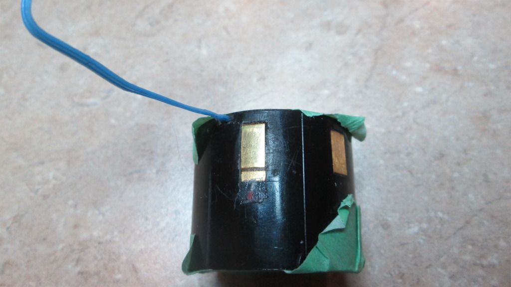
Thanks for all the help guys....I guess I have to decide whether I am OK with using this tube the way it is or get a little more creatively destructive in looking for the board as shown in Valleyrat's photo. I guess if it's to be a learning experience I should go for it, right? What would happen if I applied 4.5v to the tube rather than 3? As a jury rig, I have contemplated slipping a small watch battery coin cell in series underneath one of the AAs in the battery compartment. I am wondering if the increased voltage would lead to a more reliable "ignition" of the tube. Obviouly if 4.5v will fry the tube, I won't do that! |
|
|
|
[#10]
I don't know the voltage threshold for the psu, I would imagine there is a regulator in there to keep voltage in check.
I am the sort of personality that has to keep going until it's right, or as close to right as I can make it. I would strip out a sqare of the boot about where the board is and excavate it. Then try to re establish connection and see what happens. |
|
|
 Win a FREE Membership!
Sign up for the ARFCOM weekly newsletter and be entered to win a free ARFCOM membership. One new winner* is announced every week!
You will receive an email every Friday morning featuring the latest chatter from the hottest topics, breaking news surrounding legislation, as well as exclusive deals only available to ARFCOM email subscribers.

AR15.COM is the world's largest firearm community and is a gathering place for firearm enthusiasts of all types.
From hunters and military members, to competition shooters and general firearm enthusiasts, we welcome anyone who values and respects the way of the firearm.

Subscribe to our monthly Newsletter to receive firearm news, product discounts from your favorite Industry Partners, and more.
Copyright © 1996-2024 AR15.COM LLC. All Rights Reserved.
Any use of this content without express written consent is prohibited.
AR15.Com reserves the right to overwrite or replace any affiliate, commercial, or monetizable links, posted by users, with our own.