USA
|
Posted: 1/18/2009 10:59:54 AM EDT
[Last Edit: Hal143]
Following My65PAN’s instructions, here’s how a friend and I installed a MY65PAN 607 stock onto an NDS XM Lower. Sorry for the crappy pics but I was juggling several things at once.
607 “Pin-On” Stock Installation 1. Drilling out the lower receiver hole. First the lower receiver was squared up using a small level and clamped in a padded vice. Next using a ½ inch end mill bit, the lower receiver hole was drilled to a total depth of .365. It just started to get into the buffer retainer hole. We used a standard 19v Hand drill at medium speed, checking depth with the calipers every so often. The goal here is to drill out the lower rod hole as close to the buffer retaining hole as possible without going into it. The depth of your receiver hole may be different than mine. 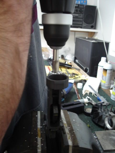
**NOTE** The buffer retaining hole slopes at a 6 degree angle downward toward the rear of the receiver. Also the recently posted authentic Colt 607 pics show the lower locking rod traversing completely through the buffer retaining hole….but that’s another story. One person drilled while the other checked for straightness. You should have a good drill, a quality sharp bit, and a steady hand to avoid any wobble. The hole came out very nice. We went the hand route, but a drill press would make for a more accurate install. 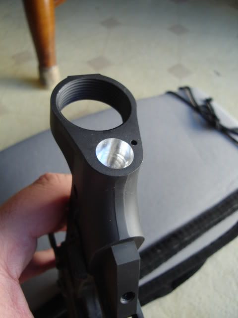
2. Measuring the locking rod. From the end face of the receiver to the bottom of the drilled lower rod hole, calculate the depth. I used the “Depth Probe” part of the caliper to calculate the depth. In my case the hole depth was .365. Yours may be different so always measure 14 times. 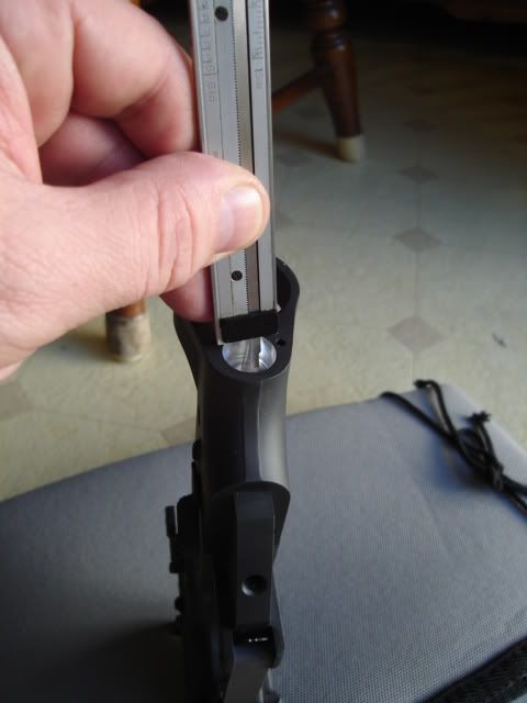
With the stock in the locked closed position, we measured .365 (The depth of our hole) from the lower lock rod lip and scribed a mark on the rod. We then added 1/16” and scribed a second mark. This extra 1/16” scribe mark is where we will make the first cut. The extra material is added, just to be safe. 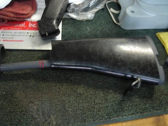
3. Cutting the rod to length. The rod was then cut using a Dremel and cut-off wheel. Kinda slow, but made for a nice cut. We then re-fit the rod to the receiver and measured again. Confident with our measurement, the last(extra) 1/16” was ground off and squared up on a grinding wheel, measuring for fit as we went along. 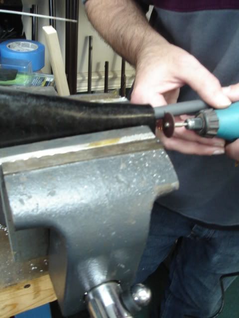
The cutting and grinding were accomplished with the stock assembled. Be sure to work slow and cool the rod with water periodically to avoid excessive heat buildup. 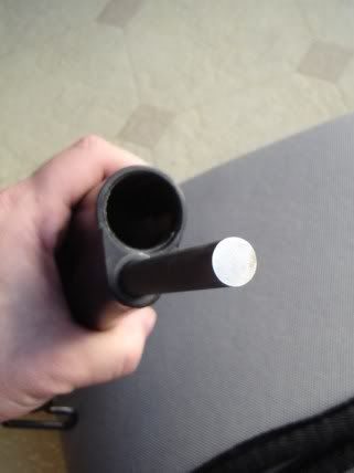
4. Shaving the buffer tube lip. Because the buffer tube lip can interfere with locking tube lip when the assembly is closed, a little material must be removed from one or the other. I just couldn’t bring myself to mess with such a beautiful stock so I opted to take a little off the bottom edge of the buffer tube lip with the Dremel. Screw the tube tight onto your lower receiver and mark the area you want to remove. The tube is an RRA Entry tube, easily replaced if need be. Remove the material. 5. Marking the cross-pin hole. You’ll see that the cross-pin needs to intersect the lower locking rod and traverse across the receiver from left to right. We eyeballed our mark from looking at many 607 photos . The cross-pin needs to capture the rear takedown pin detent spring. Roughly 1/8” - 3/16" in from the receiver end face and just below center of the rear takedown pin detent spring hole. X marks the spot. Scribe it. 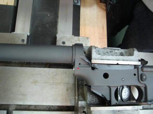
6. Drilling and seating the cross-pin hole. Now is not the time for that Guinness, or maybe it is. The lower receiver was clamped and leveled into our milling machine and the bit chucked up. My roll pin was a standard Ace Hardware tension pin 1/8 by 7/8, just like My65PAN says to use. My pin measured .129 in diameter. The bit wanted to wander a little bit at first until it got a good bite on the metal. Use a pointed center punch to tap a starter indentation. You really need a good quality sharp bit. We opted to use a smaller bit than the pin at .125. Your pin size may vary. Drill it, left side only. Insert the buffer tube and buffer retaining spring and plunger. Next LOCK the stock in the OPEN position and install the stock assembly onto the buffer tube, and insert the lower locking rod into the lower receiver hole, bottoming it out. Then wrap electrical tape nice and tight around the buffer tube and lower rod to hold them in that position. Make sure the lever lock is in the “L” position. 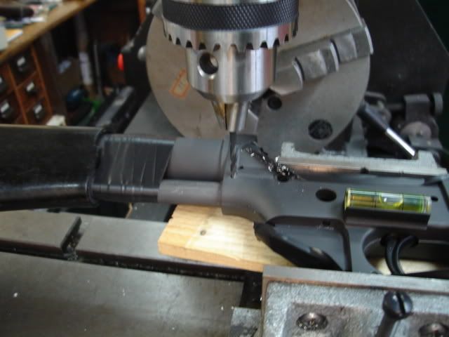
Make sure everything is clamped up tight. Align your bit through your existing hole and drill the rod straight on through to the other side of the receiver. Make sure your stock assembly is held straight and tight in the hole while drilling. 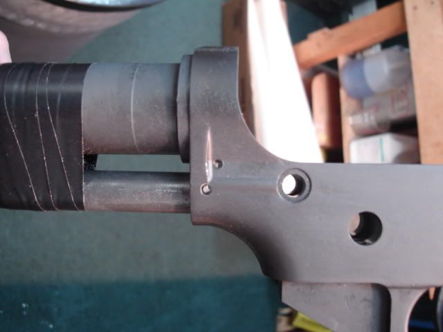
Once drilled, our roll pin was polished up and checked for burrs. Start the pin by tapping it in with a Roll Pin Holder Punch. Just get it started and stop. A little CLP helps. To install the rear takedown pin detent spring, you will need to cut off a few coils from the spring. Insert the detent, rear takedown pin, and then the spring, then use a small punch to hold the spring in place, far enough to clear the cross-pin. Then drive the pin home. 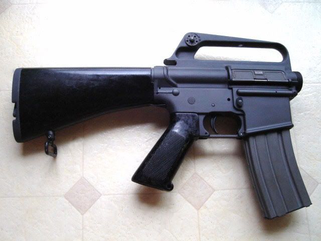
I can’t begin to describe how awesome this stock is now that’s installed. It’s tight, solid and locks up perfectly. It feels very secure and Mark’s precision machining is spot on.. The stock is truly a functional work of art. I hope this helps somebody who is hedging that 607 build for fear of boogering it up like was. Thanks Mark, Tom A. and everyone else for the info. Now did I just hear someone say 608? 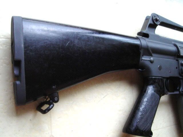
|
|
|
|
[Last Edit: my65pan]
[#1]
That is a great "how to" post Hal! I'm sure it will help a lot of folks that haven't installed their stocks yet. Thanks for taking the time to take photos and write that up.
|
|
|
|
USA
|
[#2]
Thank You Mark for offering such a great stock !
At the last minute I opted to go with an original 604 upper and the NDS XM16E1 lower instead of the NDS A1 lower. I highly recommend the stock to everyone. The install is really easier than it looks and a lot of fun. Hal |
|
|
|
[#3]
Awesome tutorial! OST for this one.
|
|
|
|
SD, USA
|
[#4]
Yes, championship material, thank you. I'm going to use a 604 upper for my 607 build also. I hope to have everything but the anodizing done by the end of next week.
|
|
|
ID, USA
|
[#5]
Awesome pics and "how to"!! Now I have no excuses
|
|
|
USA
|
[#6]
Originally Posted By retroangles:
Awesome pics and "how to"!! Now I have no excuses 1. Yes the NDS hole was very close. The lower rod would just barely fit in the lower hole, but a 1/2" end mill bit was used per 65Pans instructions. 2. If you mean the cross-pin, no, it was not drilled at 6 degrees. It was drilled straight across the lower. The buffer retaining spring hole is factory drilled at 6 degrees. They come that way from the factory. At least that's what Iv'e been told. So the bottom of the buffer retainer hole is a little closer to the rear of the receiver than the top. Hal |
|
|
ID, USA
|
[#7]
That clears everything up fer me thanks again!!
|
|
|
|
[#8]
You used a 1/2" end mill in a hand drill???

You have some fooking cajones, my friend... 
|
|
|
|
|
[#9]
Originally Posted By postino:
You used a 1/2" end mill in a hand drill???
You have some fooking cajones, my friend... I thought the same thing, but with the lower already having an existing 1/2" hole I'll bet it wasn't bad. From the pics it looks like Hals gunsmith has a Smithy Granite, I wonder why he didn't use the milling head to do that part? Either way it turned out nice. |
|
|
|
|
[#10]
Since pics of a vintage 607 show the bottom rod drilled through, has anyone gotten brave and drilled all the way through and seen if the buffer retainer spring is happy against the top of the rod?
Are the XM lowers available yet? This is exactly the kind of stupid crap I am known to try. "Z09SS! Ruining parts, so you don't have to!" |
|
|
|
|
[#11]
Originally Posted By Z09SS:
Since pics of a vintage 607 show the bottom rod drilled through, has anyone gotten brave and drilled all the way through and seen if the buffer retainer spring is happy against the top of the rod? Are the XM lowers available yet? This is exactly the kind of stupid crap I am known to try. "Z09SS! Ruining parts, so you don't have to!" worse case scenario, you have to redrill the buffer retainer hole a bit deeper and go into the top of the rod. It's pinned so it's not like it's going to move or anything. |
|
|
|
|
[#12]
Originally Posted By Z09SS:
Since pics of a vintage 607 show the bottom rod drilled through, has anyone gotten brave and drilled all the way through and seen if the buffer retainer spring is happy against the top of the rod? Are the XM lowers available yet? This is exactly the kind of stupid crap I am known to try. "Z09SS! Ruining parts, so you don't have to!" The detent wouldn't even fit, much less the spring. The rod would have to be drilled through to accept the spring and detent. I probably would have done this on mine had I known the originals where done this way. I don't think it would be difficult to do, but you have to keep in mind that the detent hole is angled at 6 degrees from vertical. |
|
|
|
|
[#13]
Bravo sir!!! Looks good!! I want mine on.
|
|
|
|
|
[Last Edit: Z09SS]
[#14]
Originally Posted By my65pan:
Originally Posted By Z09SS:
Since pics of a vintage 607 show the bottom rod drilled through, has anyone gotten brave and drilled all the way through and seen if the buffer retainer spring is happy against the top of the rod? Are the XM lowers available yet? This is exactly the kind of stupid crap I am known to try. "Z09SS! Ruining parts, so you don't have to!" The detent wouldn't even fit, much less the spring. The rod would have to be drilled through to accept the spring and detent. I probably would have done this on mine had I known the originals where done this way. I don't think it would be difficult to do, but you have to keep in mind that the detent hole is angled at 6 degrees from vertical. The originals have the pocket for the spring and detent cut into them? It just keeps getting clearer why they stopped with this design and went to the Type 2. EDIT I found this CAD file and the holes intersect more than I thought! 
|
|
|
|
USA
|
[#15]
Originally Posted By my65pan:
Originally Posted By postino:
You used a 1/2" end mill in a hand drill???
You have some fooking cajones, my friend... I thought the same thing, but with the lower already having an existing 1/2" hole I'll bet it wasn't bad. From the pics it looks like Hals gunsmith has a Smithy Granite, I wonder why he didn't use the milling head to do that part? Either way it turned out nice. Knowing nothing about machining, I handed my gunsmith friend some printed instructions and explained what to do and he was off and running. I figured he would have used the milling head too, but when I said some guys were using hand drills, he thought that sounded good to him. The lower receiver hole took about 10 minutes to do. We kept checking the depth and didn't want to get too far into the buff retainer hole. We talked about going ahead with traversing through the buff retainer hole, but discretion is the better part of valor. Now if I had a few beers, I'd a went for it.
|
|
|
|
[#16]
Originally Posted By Hal143:
Knowing nothing about machining, I handed my gunsmith friend some printed instructions and explained what to do and he was off and running. If he'd ever had an end mill (and workpiece) go flying out of a vise and embed itself in the wall, he'd probably still be running...
When I first started out, running a pantograph mill, I had a sign on my tool box..."Watch Out For Low Flying Tools"...
I've progressed since then...Unfortunately, so has CRS... ...Adapt...Improvise...Overcome... |
|
|
|
USA
|
[#17]
I'll have to ask him about that. Knowing Tom, it probably has happened to him before.
|
|
|
|
[#18]
Originally Posted By Hal143:
I'll have to ask him about that. Knowing Tom, it probably has happened to him before. It happens to even the best machinist...once... (If you're like me, you just hang a target on the wall and keep on truckin')... |
|
|
|
VA, USA
|
[#19]
Nice Job HAL143! Your post will defiantly make it allot easier. I know when I installed mine it really wasn't hard to do. The key is taking your time and don't rush it. These stocks are sweet and look like the original when installed. Mark did a great job. I think I'm going to buy another
|
|
|
ID, USA
|
[#20]
Hey mods can we get this thing stickied

|
|
|
|
[#21]
Originally Posted By postino:
It happens to even the best machinist...once... Once?
|
|
|
|
|
[#22]
Hal, can you take a close-up picture of how you modified the lip on your buffer tube? I'm curious to see what you did there as I'm sure others are.
|
|
|
|
USA
|
[Last Edit: Hal143]
[#23]
That's a tough place to get a good photo of when assembled. Sorry I didn't get an "in progress" pic.
I tightened the tube to the lower receiver and with a Sharpie marked about a 3/8" area where the lower lock rod hits the buffer tube lip. The buffer tube was placed in a vice. The lip is round and I ground a small 3/8" flat area on the bottom of the buffer tube lip. Very little material was removed to work, maybe 1/32nd. I used a dremel with a round high speed cutter bit, then a file. Now you should tighten your tube a few times to get the true bottom of where the locking rod will hit. On my final assembly I was able to tighten the tube a hair more, but still had clearance. MS Paint Area in red is material removed. 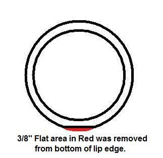
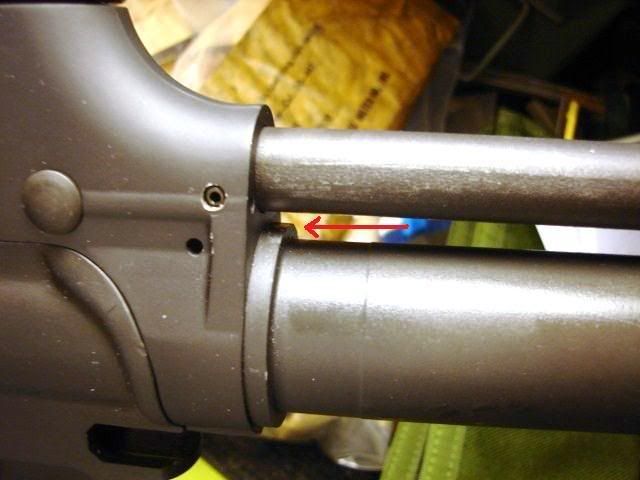
I had my buffer tube anodized XM Gray before the mod, so the area is shiny in that spot. I recommend modding the buffer tube before anodizing, though you cannot see the area when assembled. The pics are vague, but that's best I can do right now under flourescent lights. Arrows show area where material was removed. 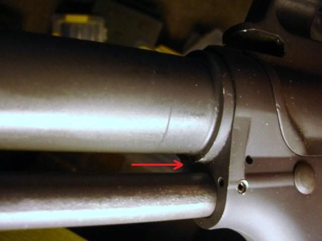
|
|
|
|
[#24]
I wish I had done mine that way now, it's hardy noticeable. Thanks for the extra pics.
|
|
|
|
IA, USA
|
[Last Edit: MarkRSims]
[#25]
This needs to be tacked, seriously.
Excellent presentation and really nice work Hal. |
|
|
USA
|
[#26]
Thanks, I just hopes it helps someone.
The process worked for my stock without any glitches. I still can't believe how solid the stock locks up. Hal |
|
|
NV, USA
|
[#27]
Very nice Hal! Thanks for the post. I wasn't going to tackle a 607 project but you have talked me into it. Is there a source for the stocks or do I keep watching EE?
Thanks again for taking the time to share. Mil-Surp |
|
|
USA
|
[#28]
Originally Posted By Mil-Surp:
Very nice Hal! Thanks for the post. I wasn't going to tackle a 607 project but you have talked me into it. Is there a source for the stocks or do I keep watching EE? Thanks again for taking the time to share. Mil-Surp Thanks milsurp, I got my stock from a member here, MY65PAN. |
|
|
|
[#29]
Originally Posted By MarkRSims:
This needs to be tacked, seriously. Excellent presentation and really nice work Hal. Poor mans tack. |
|
|
|
WA, USA
|
[#30]
Hmm or you could just bolt one on :)
|
|
|
|
[Last Edit: my65pan]
[#31]
|
|
|
|
|
[#32]
I just found this and I gotta say this is one of the coolest things I've ever seen on ARFCOM! Way to go! If only there was $ for a new retro build.
|
|
|
|
|
[Last Edit: Morg308]
[#33]
I'm really glad this got tacked. Looks like I'll have the time to tackle mine soon. Great thread.
|
|
|
|
USA
|
[#34]
Feel free to contact me if I can be of any help.
Hal |
|
|
AL, USA
|
[#35]
Originally Posted By WA-Tom:
Hmm or you could just bolt one on :) Well, while we're at it. I cut and pasted this one from the archives. I thought about pulling up the first post but this one is going to suck up some bandwidth due to the number of photos. I thought I'd share this with those looking to build the XM607 or just purchase one of the stocks that will soon be on the market. Let's get started, shall we? This is the before of the before and after photos. The XM177E2 is complete, waiting to be converted to the XM607 configuration. 
Here's the back end. 
Here's the front end. Sorry the photo is phuzzy, not sure how that happened. 
It takes a 1/8 American (Let me get a HELL YEAH!) allen wrench to get started. Simply remove the screw that retains the selector lever. 
With the screw out the lever will just slide off of the end of the shaft. The shaft can then be pushed through the stock along with the buffer tube. 
This is as far as the stock needs to be disassembled to install it on your receiver. 
This photo shows how the internal parts interact. The pin goes through the shaft which is inside of the outer tube. The outer tube controls the position of the stock via two slots which are 180 degrees opposite of each other. 
This photo shows how the spring loaded ball bearing provides just enough resistance to keep the selector lever in position. That prevents the stock from inadvertently collapsing. 
This photo shows how the end of the control shaft is assembled by welding. Looks like a pretty good job to me! 
If you are removing a stock from your receiver make sure that you don't let this spring fly out. Also take care not to kink it or bend it when unscrewing the buffer tube. 
Speaking of unscrewing the buffer tube, make sure that while you are focused on the takedown pin detent spring that you don't let this one rocket out of the receiver. It can cause physical pain, watering eyes, and severe cursing. 
These are the parts that you don't want to loose. 
This is the rear of the lower receiver ready to have the 607 stock installed. 
Notice that the nut that holds the center shaft will fit inside of the recess in the rear of the receiver. 
This is how the buffer tube and center shaft assembly should look once assembled. Don't forget to put your takedown pin, detent, and spring back in first as well as the buffer retaining detent and spring. 
This is a view from the rear. The buffer tube has no wrench flats and no screwdriver slots. It must be tightened with a strap wrench. If you are adventurous you could drill a hole through the rear of the tube and insert a rod through it. I chose to use a strap wrench. 
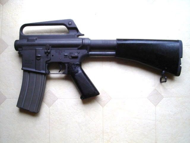
Well, now we are getting somewhere. The stock simply slides back onto the buffer tube and center shaft assembly. The selector lever and screw go back on in reverse of the order in which they came off. Don't go gorilla on the screw, just snug it up good. Use some blue loc-tite if it makes you feel better. Here it is open. 
Here it is closed. The lock up is snug in both positions with no rattling and no side to side play. It's nice and tight. 
This is the after of the before and after photos. Now it is ready to be converted to an XM177E2. We'll save that for another day. 
Here's the XM607 waiting to go to the machine gun shoot. It looks so excited I don't see how it can contain itself. 
I'll be posting some more photos after the shoot as well as an after action report on the performance of the stock. I took some measurements of the slots so hopefully there won't be much of a change there. VIDEO! 45Bravo out. |
|
|
|
[Last Edit: my65pan]
[#36]
Actually there's no need to take the TSI stocks apart to install. Just open the stock, make sure your rear takedown spring is captured, put a strap wrench on the buffer tube, and tighten it up. Done.
|
|
|
|
|
[#37]
45Bravo - that is one righteous looking 607! It ought to make waves at the MG shoot! Let us know how people like it, and how it performs.
|
|
|
|
USA
|
[#38]
During our installation process, I was limited on how many pics I could take of each little step due to being in a busy shop.
If there is a step you need described in detail, or if I can draw you a better picture of something, just IM me, or email me. Thanks, Hal143 |
|
|
|
[#39]
Hal, you did a real good job of documenting how you went about it. If my friend GunsnFins ever gets around to installing his I plan to be there to take lots of pictures to post myself.
|
|
|
|
USA
|
[#40]
Thanks Mark, I'm hearing from a couple people who are fixing to install their stocks soon.
Hal |
|
|
|
[Last Edit: my65pan]
[#41]
During this next run of stocks I'm going to try to photograph/document how I go about fitting the hardware to the donor stocks to add to the knowledge base here in the retro forum. If I do another run I'll do the same with the fabrication of the hardware.
Edit: Link to how I fit the hardware to the donor stocks. http://www.ar15.com/forums/topic.html?b=3&f=123&t=430680 |
|
|
|
CA, USA
|
[#42]
Could someone point me to where the pics of the original 607 rod being drilled all the way through? I have a stock coming from Mark, and I would like to give it a try. Thanks
|
|
|
|
[#43]
Originally Posted By missiondude:
Could someone point me to where the pics of the original 607 rod being drilled all the way through? I have a stock coming from Mark, and I would like to give it a try. Thanks Here you go. http://www.ar15.com/forums/topic.html?b=3&f=123&t=414249 |
|
|
|
CA, USA
|
[#44]
Thanks alot Mark. The stock looks great. I did not realize how far the rod went int the receiver.
|
|
|
|
[#45]
Getting the rod into the receiver will be the easy part. Getting the buffer retainer hole drilled through the rod at 6 degrees is another thing. Rigging up something on a sine plate is how I would go about it.
|
|
|
|
FL, USA
|
[#46]
Dean
If your reading this, then you've found the thread. Let me know if I can be of any more help. Hal |
|
|
IL, USA
|
[#47]
Sweet!. Does seem like quite task though
|
|
|
AR, USA
|
[#48]
I installed mine the same way Hal143 did his. I memorized his instructions, and it went off without a hitch.
The only deviation was the equipment used. I put my 1/2" centercutting end mill bit in a drillpress, and leveled my "in the white" NDS XM lower into a drillpress vise. Then I clamped the vise to the drillpress base with two bigass C clamps! Instead of using a grinding wheel to finish/square the end of the locking rod, I used an upright belt sander. If one was to try the original method of putting the rod through the buffer detent/spring area and drilling the 6 degree hole through the rod, how would one loosen and back out the buffer tube to install the retainer and spring? Or would you just disassemble the stock, install the rod and tube, and then reassemble the stock?? I could just see springs and detents being launched into orbit, so that's why I just decided to go with a tried and true method of installation. Thank you Hal143 for the excellent tutorial, and thank you my65pan for the works of art you've shared with us! |
|
|
|
[#49]
One of these days I'll get around to putting mine on.
|
|
|
|
FL, USA
|
[#50]
Originally Posted By coctailer:
One of these days I'll get around to putting mine on. Do it ! |
|
|
 Win a FREE Membership!
Sign up for the ARFCOM weekly newsletter and be entered to win a free ARFCOM membership. One new winner* is announced every week!
You will receive an email every Friday morning featuring the latest chatter from the hottest topics, breaking news surrounding legislation, as well as exclusive deals only available to ARFCOM email subscribers.

AR15.COM is the world's largest firearm community and is a gathering place for firearm enthusiasts of all types.
From hunters and military members, to competition shooters and general firearm enthusiasts, we welcome anyone who values and respects the way of the firearm.

Subscribe to our monthly Newsletter to receive firearm news, product discounts from your favorite Industry Partners, and more.
Copyright © 1996-2024 AR15.COM LLC. All Rights Reserved.
Any use of this content without express written consent is prohibited.
AR15.Com reserves the right to overwrite or replace any affiliate, commercial, or monetizable links, posted by users, with our own.