|
Posted: 4/16/2010 7:41:06 AM EDT
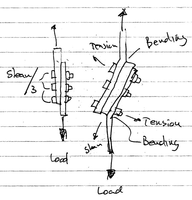
There are two designs in the image below. Let's call the top design "A" and the bottom design (the one with the
square tube) "B". Is design B inherently less strong when it comes to lateral force? That is, when the green bar is being pulled linearly in one direction and the red bar linearly in the other? Intuitively, I would say yes - because the green bar is able to exert more leverage on the bolts where they pass through the red bar. On the other hand, in theory, there shouldn't be any slide at all without the distance between the nut and the bolt head increasing. Trigonometry says so. This would see shearing loads of 3 tons and tension loads of 1 ton. ETA: Correction, the load would be spread across two of these - so 1.5 ton shearing and 1000 lbs tension. What say ye engineers. physicists, and FEA junkies? 
|
|
|
|
[#1]
I'm going to say B will be stronger since it will convert some of the load to tensile on the bolts, rather than all shear, as in A.
|
|
|
|
[#2]
Wouldn't it depend on the material of the bolts and bars? If the bar on B will bend before the bolts, then yes, otherwise, I'd say they are equal in strength.
|
|
|
|
[#3]
design B is stronger...at least from the bolt's perspective. you've created a double shear joint with design B, and bolts have 2x the shear capacity for double shear as they do for a single shear joint (design a).
-matt eta: a little confused with your terminology. is the load lateral or axial? |
|
|
|
[#4]

I think I understand your statement ... if the bolts in the lower diagram are NOT in double shear you are adding a small bending moment ... a free body diagram would be helpful. |
|
|
|
[#5]
I hate all them ME questions, EE over here. there would be (more) of a torquing force on the item in question, however, I am not sure how this would impact the breaking/failure point (which I assume would be the measure of its 'strongness').
I am at work, not home, so I cant throw the thing into solidworks and see the results, though I would imagine the answer is no, it is not inherently less strong, based purely on my guesses. |
|
|
|
[#6]
Quoted:
I'm going to say B will be stronger since it will convert some of the load to tensile on the bolts, rather than all shear, as in A. Interesting. I like it! |
|
|
|
[#7]
Quoted:
design B is stronger...at least from the bolt's perspective. you've created a double shear joint with design B, and bolts have 2x the shear capacity for double shear as they do for a single shear joint (design a). -matt eta: a little confused with your terminology. is the load lateral or axial? Oh.... I was picturing there being 3 bolts on the top, and 3 separate bolts on the bottom. So it's supposed to be one bolt all the way through? Two points of force will mean the force is distributed so I'll agree with Matt. |
|
|
|
[#8]
Quoted:
Quoted:
I'm going to say B will be stronger since it will convert some of the load to tensile on the bolts, rather than all shear, as in A. Interesting. I like it! You'll get more deflection with B, but it will hold more load, assuming that the blue material won't crush and turn it into A. Tensile strengh is stronger than shear strength. My 2 cents. |
|
|
|
[#9]
It's not possible to answer with any certainty unless one knows what each of the materials is.
|
|
|
|
[#10]
They will both fail prematurley and unexpectedly due to Murphey's Law of Fasteners from China Is All Manufacturers Use Nowadays. ....the guy who has to fix stuff like this in the field.
|
|
|
|
[#11]
Quoted:
design B is stronger...at least from the bolt's perspective. you've created a double shear joint with design B, and bolts have 2x the shear capacity for double shear as they do for a single shear joint (design a). -matt eta: a little confused with your terminology. is the load lateral or axial? Lateral? Axial? Eh... I may have the meanings of those confused. 
This is for a tow hitch that doesn't fit. (Even the manufacturer claims it does. That's another story.) The hitch will fit if it is dropped down 2". Thus the 2" 1/4" wall square tube. The red bar is actually the pickup frame. The green bar is the hitch. There would be two of these - one on the left and one on the right. Most of the towing force will be applied in a linear manner length-wise. Does that make more sense? |
|
|
|
[#12]
What, Google sketchup doesn't have an FEA pack?
|
|
|
|
[#13]
Quoted:
Oh.... I was picturing there being 3 bolts on the top, and 3 separate bolts on the bottom. So it's supposed to be one bolt all the way through? Two points of force will mean the force is distributed so I'll agree with Matt. Yeah, it would be one bolt 1/2" x 3" as opposed to one bolt 1/2" x 1". |
|
|
|
[#14]
Only one thing to do. Make one of each and try it!
|
|
|
|
[#15]
The top configuration will put the bolts into pure shear. The bottom configuration could put the bolts into combined shear and tension. Combined shear and tension could result in a prying action on the bolts, which would be the most likely mechanism of failure. Insofar as this is a trailer hitch for a pickup truck, I'd say that there's no real problem with the bottom arrangement. If you're worried about it, weld the tube to either the frame or the hitch, and bolt the tube to the other element as in the top arrangement.
|
|
|
|
[#16]
Quoted: What, Google sketchup doesn't have an FEA pack? Heh. Probably won't be long, though! |
|
|
|
[#17]
Quoted:
What, Google sketchup doesn't have an FEA pack? I don't completely hate Sketchup, but it is a pain to use when you are accustomed to Autocad. Sketchup is the only thing I have installed on this machine though. |
|
|
|
[#18]
BSME
3 votes for B?? Goes to show the genius of GD again  Both have the same shear force, but B can induce more tension and more of a moment on the bolts. A is the stronger design. |
|
|
|
[#19]
...this is why I'm a CHEMICAL engineer...
|
|
|
|
[#20]
Quoted:
Quoted:
design B is stronger...at least from the bolt's perspective. you've created a double shear joint with design B, and bolts have 2x the shear capacity for double shear as they do for a single shear joint (design a). -matt eta: a little confused with your terminology. is the load lateral or axial? Lateral? Axial? Eh... I may have the meanings of those confused.
This is for a tow hitch that doesn't fit. (Even the manufacturer claims it does. That's another story.) The hitch will fit if it is dropped down 2". Thus the 2" 1/4" wall square tube. The red bar is actually the pickup frame. The green bar is the hitch. There would be two of these - one on the left and one on the right. Most of the towing force will be applied in a linear manner length-wise. Does that make more sense? Linear manner length wise is axial load (the axis runs down the centerline and axial load is just pulling out or pushing in on that centerline.) You will see both axial and lateral loading on that hitch. But still, the same principles apply. Your example is what is called statically indeterminate in engineering terms, so the modulus of elasticity (i.e. stretchiness value of the material) comes into play to give you enough equations per variables to solve your loading values. Basically, it means when you put a load on it, the deflection (or stretch/deformation) of the material of the structure will turn some of the shear load into tension load on the bolts in design B. Thus the bolts won't experience the amount of shear as in A, per equal towing loads. |
|
|
|
[#21]
Quoted: design B is stronger...at least from the bolt's perspective. you've created a double shear joint with design B, and bolts have 2x the shear capacity for double shear as they do for a single shear joint (design a). -matt eta: a little confused with your terminology. is the load lateral or axial? I guess you think doubling the # of links on a chain makes it twice as strong also? |
|
|
|
[#22]
Quoted:
I'm going to say B will be stronger since it will convert some of the load to tensile on the bolts, rather than all shear, as in A. The load isn't converted - it's still there. Eccentricity is introduced and it resolves to a tension/compression couple. The bolts still have the original shear, but now an additional tension force. You've got to check the bolts for combined tension and shear. "B" introduces more twist. |
|
|
|
[#23]
Quoted:
BSME 3 votes for B?? Goes to show the genius of GD again
Both have the same shear force, but B can induce more tension and more of a moment on the bolts. A is the stronger design. B will experience less shear, because it turns some of that shear into tension. B is the stronger design. BSCE here. P.E. |
|
|
|
[#24]
Quoted:
Quoted:
I'm going to say B will be stronger since it will convert some of the load to tensile on the bolts, rather than all shear, as in A. The load isn't converted - it's still there. Eccentricity is introduced and it resolves to a tension/compression couple. The bolts still have the original shear, but now an additional tension force. You've got to check the bolts for combined tension and shear. "B" introduces more twist. Hell no, you can't create or destroy energy. That creation of the tension is from load taken away from the shearing. Less shear in B. Steel is stronger in tension than shear (young's modulus > shear modulus). |
|
|
|
[#25]
Quoted:
Quoted:
design B is stronger...at least from the bolt's perspective. you've created a double shear joint with design B, and bolts have 2x the shear capacity for double shear as they do for a single shear joint (design a). -matt eta: a little confused with your terminology. is the load lateral or axial? I guess you think doubling the # of links on a chain makes it twice as strong also? He's right about the bolts. You've got to fail two shear planes as opposed to one. Check Table 7-1, "Available Shear Strength of Bolts," in the AISC Manual of Steel Construction, 13th Ed. Page 7-22. |
|
|
|
[#26]
ok, he said lateral, and i assumed he was applying a load perpendicular to the long axis of the tubes/bars. i also assumed that the bolts were through bolts, the bars top and bottom were stationary and the lateral load was being applied to the tube...that is a classic double shear joint.
based on the further information, i agree with dzlbenz. |
|
|
|
[#27]
Quoted:
Quoted:
Quoted:
I'm going to say B will be stronger since it will convert some of the load to tensile on the bolts, rather than all shear, as in A. The load isn't converted - it's still there. Eccentricity is introduced and it resolves to a tension/compression couple. The bolts still have the original shear, but now an additional tension force. You've got to check the bolts for combined tension and shear. "B" introduces more twist. Hell no, you can't create or destroy energy. That tension is from load pulled away from the shearing. Less shear in B. No energy is involved. This is force. The shear is the same, shear at a distance is torque, which is resolved by a couple. Do you want a free-body diagram? |
|
|
|
[#28]
Just by observation I would say the shear load on the bolts would be less in B because of the distribution of the shear load in to two places. The bending moment in B would be greater because of the increased distance between the two plates given the same load for both examples. It all really depends on the shear capabilities of the bolts if they are not homogeneous with the material used in the bar and the tube steel.
|
|
|
|
[#29]
Quoted:
Quoted:
Quoted:
design B is stronger...at least from the bolt's perspective. you've created a double shear joint with design B, and bolts have 2x the shear capacity for double shear as they do for a single shear joint (design a). -matt eta: a little confused with your terminology. is the load lateral or axial? I guess you think doubling the # of links on a chain makes it twice as strong also? He's right about the bolts. You've got to fail two shear planes as opposed to one. Check Table 7-1, "Available Shear Strength of Bolts," in the AISC Manual of Steel Construction, 13th Ed. Page 7-22. heh. thanks. |
|
|
|
[#30]
Quoted:
Quoted:
Quoted:
Quoted:
I'm going to say B will be stronger since it will convert some of the load to tensile on the bolts, rather than all shear, as in A. The load isn't converted - it's still there. Eccentricity is introduced and it resolves to a tension/compression couple. The bolts still have the original shear, but now an additional tension force. You've got to check the bolts for combined tension and shear. "B" introduces more twist. Hell no, you can't create or destroy energy. That tension is from load pulled away from the shearing. Less shear in B. No energy is involved. This is force. The shear is the same, shear at a distance is torque, which is resolved by a couple. Do you want a free-body diagram? Yes, energy is involved. Energy = force x displacement. You have force and deflection in that structure.. That's energy.. Even with just force, using static structures, equilibrium of force applies, which is the same idea. Newton's laws of classical physics. |
|
|
|
[#31]
|
|
|
|
[#32]
Quoted: Quoted: BSME 3 votes for B?? Goes to show the genius of GD again Both have the same shear force, but B can induce more tension and more of a moment on the bolts. A is the stronger design. B will experience less shear, because it turns some of that shear into tension. B is the stronger design. BSCE here. P.E. You need to revisit your books einstein. This reminds me of the thread where I was arguing against 3 EEs and 3 electricians who said a circuit with a resistor draws the same current as a similar circuit without Static load, the shear is the same. Draw up your FBD, draw your rectangle around the tube and top plate, it's the same. Or we can go Gedanken as the real Einstein would do, imagine that tube as being 10' wide. Same shear, much greater tension. I hope you didn't design any bridges I've driven on. |
|
|
|
[#33]
Quoted:
Quoted:
Quoted:
BSME 3 votes for B?? Goes to show the genius of GD again
Both have the same shear force, but B can induce more tension and more of a moment on the bolts. A is the stronger design. B will experience less shear, because it turns some of that shear into tension. B is the stronger design. BSCE here. P.E. You need to revisit your books einstein. This reminds me of the thread where I was arguing against 3 EEs and 3 electricians who said a circuit with a resistor draws the same current as a similar circuit without
Static load, the shear is the same. Draw up your FBD, draw your rectangle around the tube and top plate, it's the same. Or we can go Gedanken as the real Einstein would do, imagine that tube as being 10' wide. Same shear, much greater tension. I hope you didn't design any bridges I've driven on. This is not a static problem sir. It's an indeterminate structure. The deflection from the elasticity of the material causes a portion of the shear to transform to tension in the bolts, which reduces the shear in the bolts. E.g. when the bolts bend slightly, they're no longer in 90 degree to the load.. |
|
|
|
[#34]
Quoted: I'll just knock it out in Catia..... EDIT: I don't even need catia this is a simple FBD. I'll get to this later. |
|
|
|
[#35]
Bore the box tube for crush sleeves in the bolt holes, weld both ends of the sleeves in. Fit plates to the ends of the box tube to close both ends, and weld.
Use grade 8 bolts in the OEM diameter, sized to keep most of the thread out of the joint. Lem |
|
|
|
[#36]
Quoted: B will experience less shear, because it turns some of that shear into tension. B is the stronger design. BSCE here. P.E. Mmmm ... I don't think so. The shear load is the shear load, regardless of the presence of any tensile load in the fastener. The limit state for the connection is most likely shear, so if the connection fails in shear in A, it'll fail in shear in B at the same applied load. The only benefit you get fro tenile activation of the bolt is a higher clamping force between the connected parts, but that will only be manifested in the connection up to the point of yield in the fastener. The tension gets into the bolts in B through elongation of the distance between the connected plies as the bottom bar is moved longitudinally with respect to the top bar. Whatever force is required to produce that linear displacement is translated to the fastener as pure shear. Since you're now in a combined-stress situation, you've got to take deductions in both shear and tensile capacity of the fastener. IT it theoretically possible, though, to install the fastener with enough preload so as to prevent any prying action, although the value of the force to create prying would be difficult to estimate for this case. It would take a couple of hours with some Roark's and some Blodgett to really come up with something reliable. |
|
|
|
[#37]
Quoted:
Quoted:
I'll just knock it out in Catia..... EDIT: I don't even need catia this is a simple FBD. I'll get to this later. Good luck with that. This problem can't be solved with just a simple FBD and static vector mechanics. You need to use 300/400 course level engineering. |
|
|
|
[#38]
Quoted: Quoted: Quoted: design B is stronger...at least from the bolt's perspective. you've created a double shear joint with design B, and bolts have 2x the shear capacity for double shear as they do for a single shear joint (design a). -matt eta: a little confused with your terminology. is the load lateral or axial? I guess you think doubling the # of links on a chain makes it twice as strong also? He's right about the bolts. You've got to fail two shear planes as opposed to one. Check Table 7-1, "Available Shear Strength of Bolts," in the AISC Manual of Steel Construction, 13th Ed. Page 7-22.  The stupidity in GD amazes me, even among engineers who don't even know the basics of mechanics. Double shear strengths only apply when you need to shear both planes for failure. ie if a force were applied to the blue tube in one direction, and an force to the red/green plates in the opposite direction. see the bottom illustration  That's not the case as stated in the OP. Here, only on plane needs to be sheared. |
|
|
|
[#39]
I do not consider these bolts to be in double-shear, since the force is only transmitted and resisted by the outer plies. The inner ply (or plies) serve only as shims. Adding a shim to a single-shear connection does not magically transform it into a double-shear connection. Never has, never will...
ETA: Mateba's picture is, well, picture-perfect. |
|
|
|
[#40]
B is stronger because it's got more stuff on it.
|
|
|
|
[#41]
With design 'B', the bending moment will bend the upper and lower bars (presumably), this will redistribute the shear force on three bolts (as in the 'A' design) to tension and shear. However, the tensile loading will be greater in the two outer bolts, and may exceed their design limits. Also, how will the bars react to the bending and tensile actions? I think Design 'A' is most likely stronger and better, particularly if there are dynamic or repetitive loads.
|
|
|
|
[#42]
Quoted: B is stronger because it's got more stuff on it.  The added stuff is a fruity-sissy color, thereby weakening the connection. |
|
|
|
[#43]
P.E. Not picking on anyone in particular, but when truthers claim that they have (insert made-up number here) Professional Engineers who are on their side, I immediately discount the claim as lending any credence to their whacko theories. Engineers are wrong about a lot of things, all the time. |
|
|
|
[#44]
If one shear plane is good, and two are better, then FOUR should kick some serious ass. Tell me this isn't stronger than a chimpanzee/Chuck Norris hybrid:
 |
|
|
|
[#45]
Quoted:
It's not possible to answer with any certainty unless one knows what each of the materials is. The red bar is whatever Dodge used to make pickup frames from. The green bar is whatever Curt Manufacturing made the hitch from. The blue tube is some mystery 1/4" wall steel that is killing my sawzall blades. So, it is all mostly unknown. |
|
|
|
[#46]
Quoted:
Quoted:
Quoted:
Quoted:
Quoted:
I'm going to say B will be stronger since it will convert some of the load to tensile on the bolts, rather than all shear, as in A. The load isn't converted - it's still there. Eccentricity is introduced and it resolves to a tension/compression couple. The bolts still have the original shear, but now an additional tension force. You've got to check the bolts for combined tension and shear. "B" introduces more twist. Hell no, you can't create or destroy energy. That tension is from load pulled away from the shearing. Less shear in B. No energy is involved. This is force. The shear is the same, shear at a distance is torque, which is resolved by a couple. Do you want a free-body diagram? Yes, energy is involved. Energy = force x displacement. You have force and deflection in that structure.. That's energy.. Even with just force, using static structures, equilibrium of force applies, which is the same thing. Newton's laws of classical physics. There is no movement; it is a static structure. If it moves, we're no longer in the realm of statics. We're not dealing with energy at all. The assumption of statics is that the bodies are rigid and deflections are about 0. Equilibrium for a determinate structure requires three equations: Sum of vertical forces = 0 Sum of lateral forces = 0 = imposed shear - resisted shear Sum of moments about a point = 0 = shear x distance - tension or compression x bolt gage. This thing is essentially a bracket hanging off a wall. The bolts pull out or push in, but also resist sliding. It is an eccentricity normal to the plane of the faying surface. I won't argue with you - you're over your head. See the AISC Manual, pp 7-9 through 7-10. When I design a bracket, I design the connections for the full shear and the full tension induced by the eccentricity. Anything else would be stupid and foolish. |
|
|
|
[#47]
Quoted: It's not possible to answer with any certainty unless one knows what each of the materials is. facepalm.jpg It's certainly possible to analyze the problem without knowing anything about the materials or loads of phase of the moon or sexual proclivities of anyone installing a trailer hitch to a pickup truck. If you don't like that answer, let me respond in a different manner: the connected parts are all ASTM A36, and the bolts are 1/2" SAE Grade 5. Now, what's the answer? |
|
|
|
[#48]
Quoted: Quoted: Quoted: Quoted: BSME 3 votes for B?? Goes to show the genius of GD again Both have the same shear force, but B can induce more tension and more of a moment on the bolts. A is the stronger design. B will experience less shear, because it turns some of that shear into tension. B is the stronger design. BSCE here. P.E. You need to revisit your books einstein. This reminds me of the thread where I was arguing against 3 EEs and 3 electricians who said a circuit with a resistor draws the same current as a similar circuit without Static load, the shear is the same. Draw up your FBD, draw your rectangle around the tube and top plate, it's the same. Or we can go Gedanken as the real Einstein would do, imagine that tube as being 10' wide. Same shear, much greater tension. I hope you didn't design any bridges I've driven on. This is not a static problem sir. It's an indeterminate structure. The deflection from the elasticity of the material causes a portion of the shear to transform to tension in the bolts, which reduces the shear in the bolts. E.g. when the bolts bend slightly, they're no longer in 90 degree to the load.. Once again, we got an engineer who vaguely remembers terms from his books, but doesn't understand what it means. This is a static problem if there ever was one. THIS is a indeterminate structure:   Shear stress = lateral force/area The lateral force does not change, neither does the cross sectional area of the bolt. The shear stress does not change einstein. What does change is the tension on the bolt. A slight deflection can elongate the bolt (strain) and even a few thousands of an inch can cause a large increase in tension.  For christ's sake, I haven't even worked as an engineer in 10 years and I remember this stuff. Scary that we got "PEs" running around designing bridges without even so much as a clue. |
|
|
|
[#49]
the answer is "c" buy another hitch.....
|
|
|
|
[#50]
Quoted:
If you don't like that answer, let me respond in a different manner: the connected parts are all ASTM A36, and the bolts are 1/2" SAE Grade 5. Now, what's the answer? The answer is B because it's got more ASTM A36 in it. |
|
|
 Win a FREE Membership!
Sign up for the ARFCOM weekly newsletter and be entered to win a free ARFCOM membership. One new winner* is announced every week!
You will receive an email every Friday morning featuring the latest chatter from the hottest topics, breaking news surrounding legislation, as well as exclusive deals only available to ARFCOM email subscribers.

AR15.COM is the world's largest firearm community and is a gathering place for firearm enthusiasts of all types.
From hunters and military members, to competition shooters and general firearm enthusiasts, we welcome anyone who values and respects the way of the firearm.

Subscribe to our monthly Newsletter to receive firearm news, product discounts from your favorite Industry Partners, and more.
Copyright © 1996-2024 AR15.COM LLC. All Rights Reserved.
Any use of this content without express written consent is prohibited.
AR15.Com reserves the right to overwrite or replace any affiliate, commercial, or monetizable links, posted by users, with our own.


