|
Posted: 9/25/2014 3:52:40 PM EDT
I could use a sanity check here. I getting deep into the realm of striplines which I only barely understand.
A while back, I posted a thread which included a digital power meter I was working on (from the article by VE2LJX). Part of that is a -40 dB tap to sample the power on a transmission line. Well, I built it and it works fairly well up to 2 meters, but quickly sucks above that. Here are my original pics: 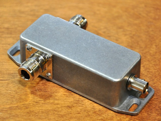 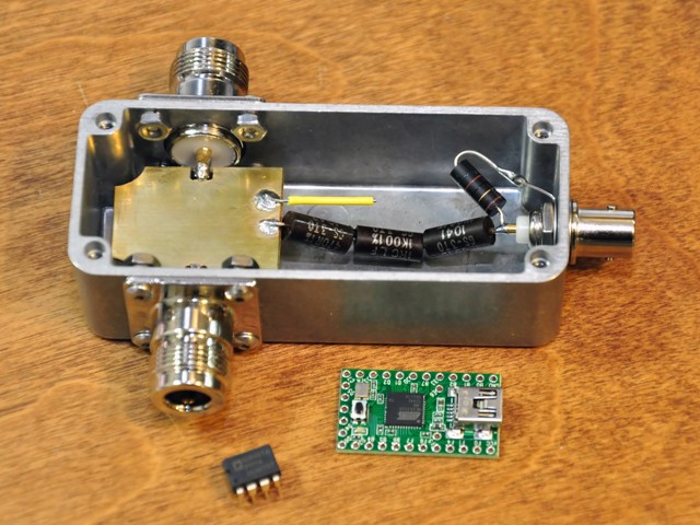 Now that I have better lab equipment, I'm trying to improve on it. A comment from AR-Jedi in my original thread has been stirring in my brain since then. I used an online microstrip calculator tool to figure out the air gap distance for a 1/2" diameter brass disk (the mainline conductor) which came out to about 1/4" above & below. So I'm thinking about machining a housing from brass to make such a cavity. Then the resistor network for the sample port can be redesigned with SMD power resistors to get me right on the desired 2475 ohms (the current one is 2460 ohms). I just don't know how to simulate this or verify the design before building it. I also have no clue whether a round disk is good. Here are top and side view of what I'm thinking about: 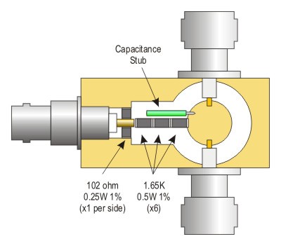 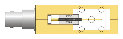 There is Teflon as the dielectric for the resistor channel instead of air because I figured I could pre-solder the internals, assemble everything with a thin layer of solder past between the housing halves and run it through reflow to permanently seal everything. The Teflon would ensure the resistors don't shift. I could still adjust (trim) the capacitance stub before doing that though. Here's the equivalent circuit: 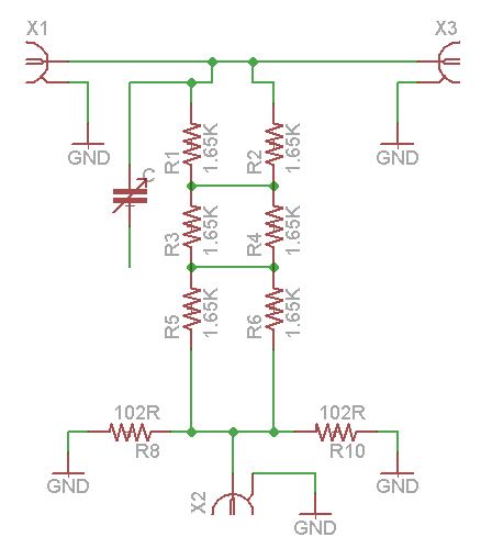 And while we're here, this is how the current one performs (too sucky for UHF measurements): Coupling: 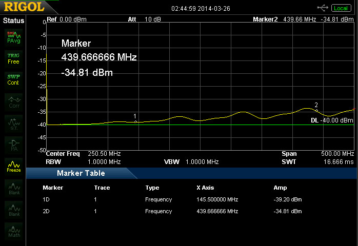 Mainline SWR / Return Loss: 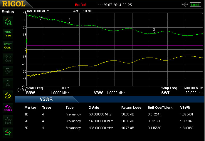 Any ideas or suggestions on how to do it right the first time without having to build a random variety of housings? |
|
|
|
[#1]
Changed up the resistor values and updated the diagrams for a better match. Maybe if the internal impedances are good, that capacitance stub could go away.
|
|
|
|
[#2]
Oh dang.
No idea how much time this will cost me. Curse you! Posted Via AR15.Com Mobile |
|
|
|
[#3]
LOL!
 Come on Stimpy, you and I can figure this out!  The resistors are on the way, the connectors are already in hand and I'm headed into town tomorrow for brass bar stock. |
|
|
|
[#4]
Fine...F-it.
If you need anything machined let me know. Posted Via AR15.Com Mobile |
|
|
|
[#5]
This might perform better and will certainly be easier to make. I bought the brass today. Wanted to make it out of copper, but they didn't have the right size in stock.
I should be able to do the machine work Sunday and the resistors will be here on Monday. We'll see! 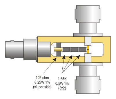 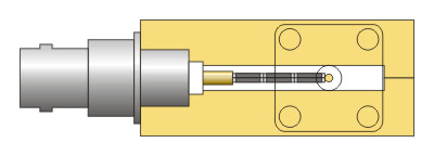 Stimpy, if you want to make one, I'd be happy to post or send you a dimensioned drawing, part numbers and whatever else you might want. Or if you have any contrary thoughts, let's hear 'em! |
|
|
|
[#6]
I am just trying to keep up on this one.
Don't think I need one of these just yet but will not refuse your offer, please send docs. I like the new design much better...cleaner and simpler, but haven't had a chance to check your math. Posted Via AR15.Com Mobile |
|
|
|
[#7]
Success! The package from DigiKey arrived sooner than expected. Assembly is complete and the test results look good, but I'll post those tomorrow after verification.
There were some interesting challenges during assembly, namely making good electrical connections to ground. The mainline grounds were no problem, but for the BNC tap port, I slathered the threads with solder paste and heated the housing until it flowed. Then soldering the 102 ohm resistors to the housing was problematic due to the extreme thermal mass. Here are the guts after soldering, ready to seal 'er up: 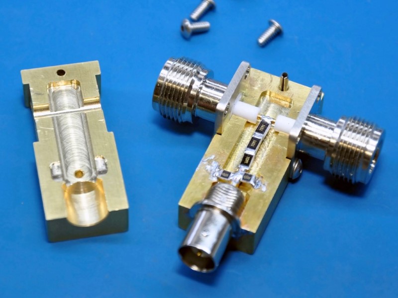 It's small compared to the old one! 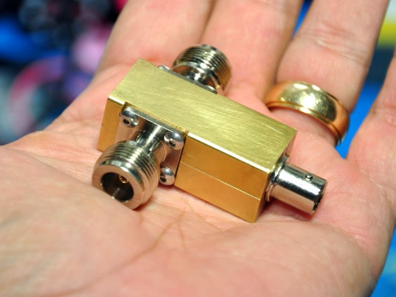 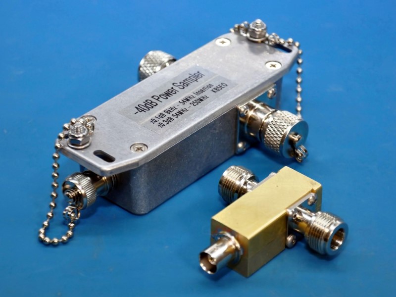 More to come . . . |
|
|
|
[#8]
Maybe try this with the resistors.
http://www.w6pql.com/video/ldmos2copper.wmv Might have to do it before installing the connectors. I like the small package. I am curious to the outcome of your test. I know the ANAN guys would love to have something small like this for Pure Signal feedback. Scroll down to May-1-2014 Their port is -16dbm This is the sensor some Anan owners are using. http://www.wavenode.com/ |
|
|
|
[#9]
Thanks, SandHillsHillbilly. I have the stuff to do that and it didn't even occur to me to use it. I've got a hot plate and an aluminum heat spreader with a thermocouple embedded in it. The whole deal is managed by a PID controller.
I'll do that on the next one. And speaking of the next one, here are some learnings from this one:
Here's another pic and some measurements, starting with the return loss setup: 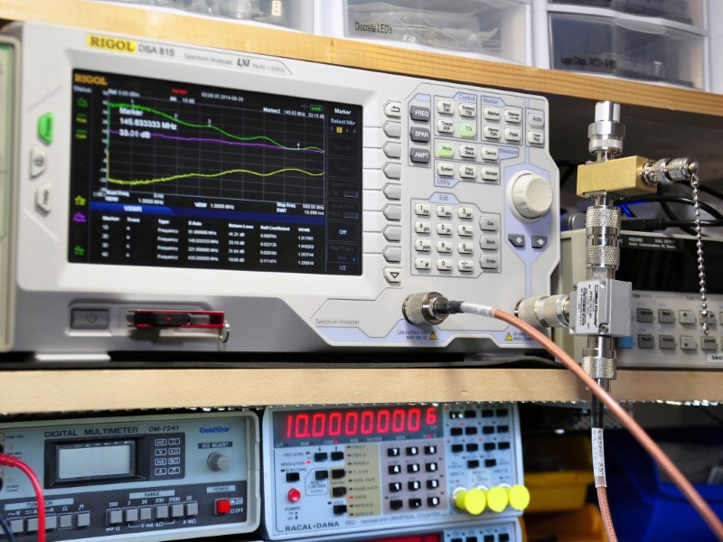 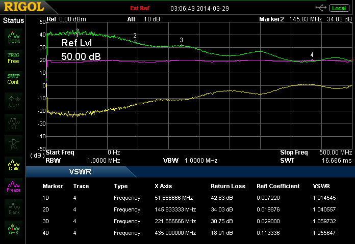 Insertion loss: 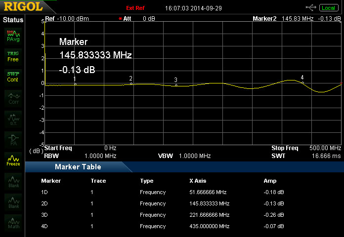 Coupling factor (much better!): 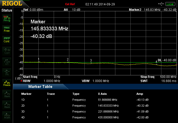 |
|
|
|
[#10]
|
|
|
|
[#11]
You seem to be on the right track.
The capacitance is to cancel resistance inductance. Here is almost the identical sampler that you are working on. Notice how flat his traces are, http://roland.cordesses.free.fr/rfcoupler.html Notice it appears there is an insulated wire parallel to the resistors. I assume he is trimming the length to achieve needed capacitance. 
You can also increase the power resistors to 10K 2W and have a -60db coupler for use with an amplifier. |
|
|
|
[#12]
Very cool. Yes, the insulated wire is to add capacitance at higher frequencies. I think adding that in to my design will help with UHF. Hopefully I'll try that tomorrow. There's enough room.
Comparing this new one to the old, I have renewed respect for W7ZOI's* original design. I figured putting a tad more science into the microstrip aspect would help and it did, but the difference isn't huge. Funny you mention QRO. It would be fun to build a high power version of this! Scaled up for 60 dB with bigger resistors, Teflon dielectric and 7/16 DIN connectors, that would be a neat build. Too bad I don't have an amp. I really wanted 1W or 2W resistors, but for SMT in this value, the best I could do with DigiKey was 1/2W. They're arranged in two parallel strips of 3, so I guess that's 3W total, which is twice the wattage of W7ZOI's design. Now, I see Mouser stocks 1.65K 1% 2512 resistors with a 1W rating. DOH!!! Which brings us to the next adventure: I really, really, really want to build a high quality, compact directional coupler ~100 - 200W, also with about 40 dB coupling. I see a lot of info on the net, but nothing that teaches me what design attributes contribute to flat coupling and good directivity & frequency response. There appears to be precious little educational info on how they work, how to design them, etc. Maybe my Googlefu is weak? *This last Field Day, a new Tech was working a pile up on my station with me logging for him. He worked W7ZOI. It took great restraint on my part to keep from ripping the mic out of his hand and talking to one of my ham radio heros. |
|
|
|
[#13]
Quoted:
*This last Field Day, a new Tech was working a pile up on my station with me logging for him. He worked W7ZOI. It took great restraint on my part to keep from ripping the mic out of his hand and talking to one of my ham radio heros. You should have FOne it! People love that stuff, as long as it is kept respectful and short. ETA - sorry I couldn't get up to speed on this one, I have been in the hospital since Sunday with rhabdomyolysis. The treatment makes it hard to do any serious thinking. Posted Via AR15.Com Mobile |
|
|
|
[#14]
I had to look that up. ZOMG! I hope you're OK! Prayers are with ya, man.

|
|
|
|
[#15]
Quoted:
[ ETA - sorry I couldn't get up to speed on this one, I have been in the hospital since Sunday with rhabdomyolysis. The treatment makes it hard to do any serious thinking. Posted Via AR15.Com Mobile Dayum I hate to hear that. I too had to look it up. That is some scarey chit. Take care & get well |
|
|
|
[#16]
I don't know shit about these things, but it sure does look nice!
|
|
|
|
[#17]
Thx guys...things are improving.
Posted Via AR15.Com Mobile |
|
|
|
[#18]
Quoted: I don't know shit about these things, but it sure does look nice! |
|
|
|
[#19]
New and improved! I finally got around to adding a capacitive compensation stub inside the tap and it works! After soldering in, trimming, re-trimming, removing and replacing it 4 times, I finally got it right. It's amazing what a difference only 0.050" makes.
Here's how the stub ended up. It's made of ordinary #22 PVC insulated hookup wire:  And here's an interesting comparison that shows the effect this simple stumpy bit of wire makes in coupling. We're looking to keep the response as flat as possible around -40 dB across a wide range of frequencies. Here is a 0 - 600 MHz sweep. The traces are as follows:
 This is exciting because it's reasonably flat up to 1 GHz. I built a correction table for it in the spectrum analyzer to null the ripples and get flat measurements. Really, it's probably best to keep measurements below 800 MHz, but hey! Now a little note regarding VSWR: Please disregard EVERYTHING I said above about VSWR measurements. Something is wrong with my setup and I'm not getting reasonable measurements on anything. Even my Minicircuits calibration load precision terminator shows ~2.1:1 VSWR. I may have pulled a stupid at some point & blown up my return loss bridge. |
|
|
|
[#20]
And while we're at it, I rebuilt the original version because I accidentally twisted the BNC and broke the damn thing. This was a chance to notch the mainline so the resistor chain can be straight, install a new capacitance stub and replace the giant axial 51 ohm shunt resistor with two 102 ohm SMD resistors. Now it's good up to about 500 MHz and capable of handling >250 watts.
  Because of my problems measuring VSWR (above), I still don't know what the internal impedances are, but I do know that it makes a big difference to have the cover on. If anybody has any suggestions for improvements or corrections, please lay it on me! I'm learning a bunch here. |
|
|
|
[#21]
Pretty amazing, BlammO! I've been looking for a tap, or a dummy load with a tap, for up to legal limit though I currently never run more than half that. Since I just want to be able to monitor my signal and don't care about the exact power level my search is fairly easy. Of course I came across projects like yours in my search though, and I can appreciate how much work you've put into it and what a great job you've done. Keep up the good work and let me know if you ever make one that will handle more power. You could go into business...
|
|
|
|
[#22]
The man's a genius...and an anteater...just wow. |
|
|
|
[#23]
 I have XCRMonger to thank for capturing my true personality. OK, so it's actually my pretend alter-ego. LOL. I have XCRMonger to thank for capturing my true personality. OK, so it's actually my pretend alter-ego. LOL.For anyone who is interested, I got my copper bar stock and Teflon dielectric. As soon as a little care package arrives from Mouser tomorrow, everything will be in place to build the next version. It'll be 1/4" shorter too, thanks to a 4-hole flange type of BNC connector. w00t! And KwaiChangCaine, challenge accepted. There will likely be a 2 kW 60 dB version in the future. The Teflon dielectric should make that practical. It may not be soon, but that seed is planted in my tiny brain now and there's no turning back. |
|
|
|
[#24]
Quoted:
For anyone who is interested, I got my copper bar stock and Teflon dielectric. As soon as a little care package arrives from Mouser tomorrow, everything will be in place to build the next version. It'll be 1/4" shorter too, thanks to a 4-hole flange type of BNC connector. w00t! a suggestion before you stick the endmill into the collet... i know it's a pain in the ass, but try to make the cavity itself as dimensionally small as possible. you are looking to minimize both the longest dimension AND the volume. doing so will flatten out your UHF performance and extend the usable range of the tap. this is one reason (of several) why you would never be able to duplicate the performance of your milled version using the hammond box version. if i can figure out how to safely take apart one of the reference Rohde & Schwarz taps/terminators we use in the lab i'll take a picture for you. these suckers are bomb-proof, good to daylight frequencies, and are designed by Germans who would consider working for Mercedes as "slumming it". ar-jedi |
|
|
|
[#25]
Jedi, this is YOUR fault!
So now you got me thinking again. Should I be sizing the dielectric cavity for a 50 ohm TL? Or does it only matter on the mainline? The new plan eliminates the cavity opposite the resistor chain (on the other side of the mainline). That oughtta help a tad too. |
|
|
|
[#26]
Quoted: if i can figure out how to safely take apart one of the reference Rohde & Schwarz taps/terminators we use in the lab i'll take a picture for you. these suckers are bomb-proof, good to daylight frequencies, and are designed by Germans who would consider working for Mercedes as "slumming it". ar-jedi  DOOO EEET!!! DOOO EEET!!! |
|
|
|
[#27]
Quoted:
Jedi, this is YOUR fault! So now you got me thinking again. Should I be sizing the dielectric cavity for a 50 ohm TL? Or does it only matter on the mainline? The new plan eliminates the cavity opposite the resistor chain (on the other side of the mainline). That oughtta help a tad too. the thru-path has to look as close as possible to 50ohm impedance. by butt-ending the chassis mount N connectors, you are doing pretty good, which your measurements support. the tap-path is less critical, especially since it has actual resistance. i would say that the stub length of the overall tap should be minimized, because the longer that gets (esp with multiple resistors) the more impedance "bumps" you have. i'm catching myself here because in my mind with the skillset you have you could easily end up with a Narda- or HP-quality tap with ruler flat performance up to a couple of GHz. but that's probably not what you had in mind when you started, just getting good performance out to 70cm would be sufficient -- and you are certainly there already. if you want to keep going up in freq just note that your T&M setup is going to start playing a role as well, Mr Heisenberg starts to screw with you and the next thing you know you are trying to work out how the device under test is interacting with the overall test environment. speaking of Narda or HP/Agilent, any time you go to a junk-fest, you should take a look at what is on the table just in terms of design approach. the microwave stuff from Narda is exceptionally well designed -- very compact, high performance, and built to last. somewhere you mentioned about learning about the theory and implementation of directional couplers (essentially, a tap that measures the power going in one direction, or the other); building a directional coupler for the 2m or 70cm range is essentially a course in E&M. you'll find out very quickly that stripline/microstrip geometry errors and cavity interaction issues turn the coupler into a poorly performing filter. for this reason it's always a good idea to look at how high performance devices were constructed, because there are many fine points to getting good results. it is much a mechanical design problem as an RF design problem. ar-jedi |
|
|
|
[#28]
ps since you seem to be interested in bedtime reading material, here is something to ponder... past a frequency of 2GHz or so, you can no longer ignore the surface roughness of the PCB trace (stripline/microstrip, etc): http://www.polarinstruments.com/support/si/AP8155.html http://www.alterawiki.com/wiki/Modeling_Copper_Surface_Roughness_for_Multi-gigabit_Channel_Designs http://www.microwavejournal.com/blogs/2-judy-warner/post/17127-keepin----it-smooth--how-surface-roughness-impacts-high-performance-pcbs |
|
|
|
[#29]
Holy cow, I never thought about surface roughness on that scale being a factor and certainly wouldn't have thought that it would start appearing around only 2 GHz. Great articles -- thanks!
Glad you mentioned directional couplers. That's the next thing I want to build. I've downloaded every PDF I can find on the topic and read every web page (except for the multi GHz stuff, because I'm mostly interested in <500 MHz for now). But I still know almost nothing about what attributes influence directivity, flatness, etc. I think I'm OK on general coupling factor and insertion loss though. I'd like to build high accuracy 40 dB dual directional couplers for HF and VHF/UHF (separate devices, I'm sure) at typical (non-QRO) power levels. I just seem to be at a brick wall for learning about design attributes. But I have some experiments planned to get a better sense of wuzzaaaap. One other thing I don't quite understand is how the power rating of the resistors relates to total power handling ability. The way I figure, the attenuator is giving me -40 dB relative to the original signal so we put 100 watts (50 dBm) through and we should have 0.01 watts (10 dBm) at the sample port. We're just pulling 10 milliwatts through the resistor chain (voltage divider), right? But VE2LJX points out that W7ZOI's original tap with three 1/2 W resistors can only handle 75 W (~48.75 dBm) on the mainline (and that means only 7.5 mW at the sample port). He goes on to say that by using 3W resistors, power handling is 200 watts (~53 dBm) on the mainline. That's not a linear proportion. My research on voltage dividers hasn't led me to an understanding yet. Forging ahead! |
|
|
 Win a FREE Membership!
Sign up for the ARFCOM weekly newsletter and be entered to win a free ARFCOM membership. One new winner* is announced every week!
You will receive an email every Friday morning featuring the latest chatter from the hottest topics, breaking news surrounding legislation, as well as exclusive deals only available to ARFCOM email subscribers.

AR15.COM is the world's largest firearm community and is a gathering place for firearm enthusiasts of all types.
From hunters and military members, to competition shooters and general firearm enthusiasts, we welcome anyone who values and respects the way of the firearm.

Subscribe to our monthly Newsletter to receive firearm news, product discounts from your favorite Industry Partners, and more.
Copyright © 1996-2024 AR15.COM LLC. All Rights Reserved.
Any use of this content without express written consent is prohibited.
AR15.Com reserves the right to overwrite or replace any affiliate, commercial, or monetizable links, posted by users, with our own.