|
Posted: 8/30/2014 6:06:44 PM EDT
Here is the build in progress:
Pelican 1520 with panel mount 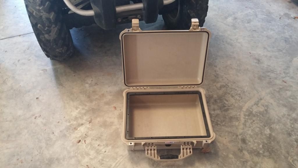
7075 T6 .071 aluminum baseplate with 1223BBM and Rigrunner 4 USB. Held to plate by industrial velcro underneath feet as well as visible straps. The straps are 5/8 velcro cable wrap, and they run through slots in the plate on the inboard side and notches on the outboard side. The plate will attach via velcro to the case. 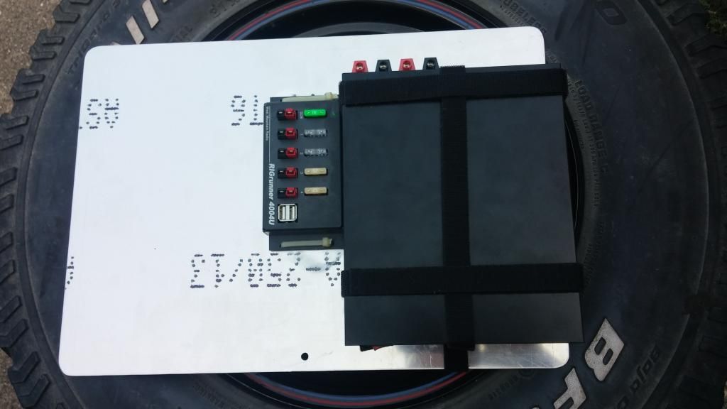
And the top plate. Also T6, coated in Aluma Hyde. The 281a radio will sit to the left of the door. Eventually a 480Sat head unit will be to the upper right of the door, with the body of the radio mounted underneath with the power supply. The top plate will be mounted inside the panel mount. 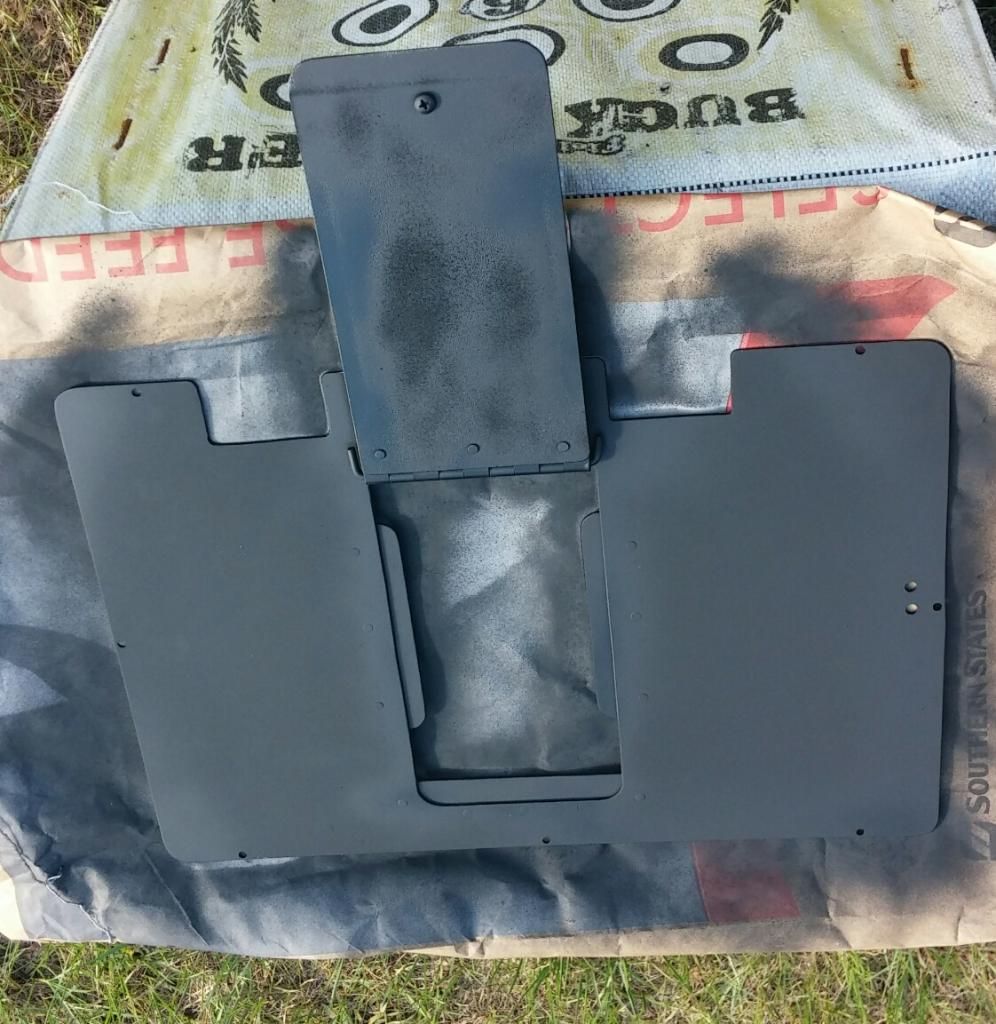
Just got the bottom panel wired up. There is a 25amp inline fuse on the hot leg between the power supply and the voltage meter. I will be using powerpole type connectors to hook an external battery to the VM when AC is not available. The load is fused through the Rigrunner, so I omitted adding another inline fuse on the load leg. I purchased the PowerCrimp ratcheting crimpers, some 10 gauge dual wire, and some 45amp powerpole plugs to wire it all with. The crimpers make it very easy to get a solid connection, I would recommend them if you use Powerpoles. I am going to pick up a thing of 25 amp fuses next time I'm at the store, and velcro it to the top of the PS so I have onboard spares. The radio won't be here til Tuesday, so expect an update on it when it arrives. As it is the door gives me massive access to the inside so I went ahead and installed the lid. Pelican calls out for a metric size, but it is just a 6/32×1/4 machine screw. Had a bunch laying around, the panel mount does not include them so be sure to acquire some to match the thickness of your plate material if going this route. 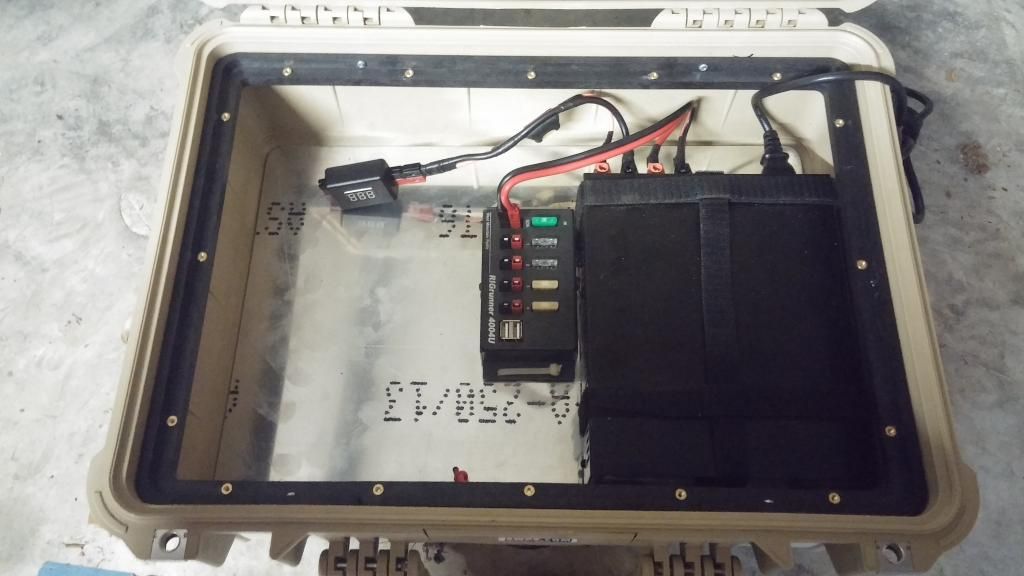
Here's a shot with the top plate installed. I ran out of velcro, but the whole inside of the lid will be covered and trimmed square when I pick up another roll. Note my fancy clock set to UTC time. The radio will mount to the left of the lid, leaving the right side empty to store headphones while traveling, and support a notepad or tablet when operating. I will be adding a remote head HF radio at some point, with plans to place the head to the right of the door, near where the cord is now. The cord can be relocated out the left hole if it becomes a nuisance. 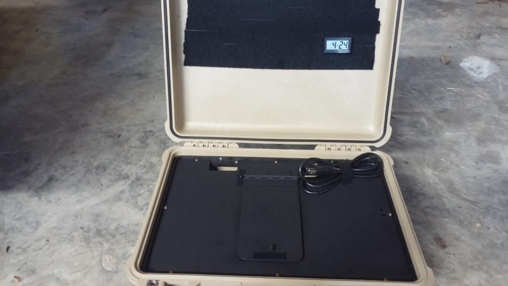
And finally for tonight, a shot of the door opened. To run DC I can just open the door and plug in the feed cable, VM is already there and ready to go. The large door can also be opened in hot weather to provide improved ventilation for the components down below. The door is held shut by velcro, and is hinged with an old piece of aircraft hinge. 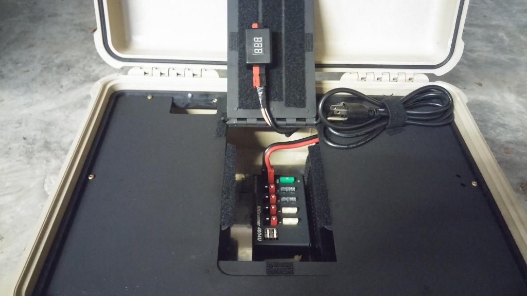
Below is a drawing showing the stiffeners holding the door assembly in place when closed. You can see them around the rim of the hole in the above photo. The rivets are all flush and invisible. They are solid, bucked rivets. 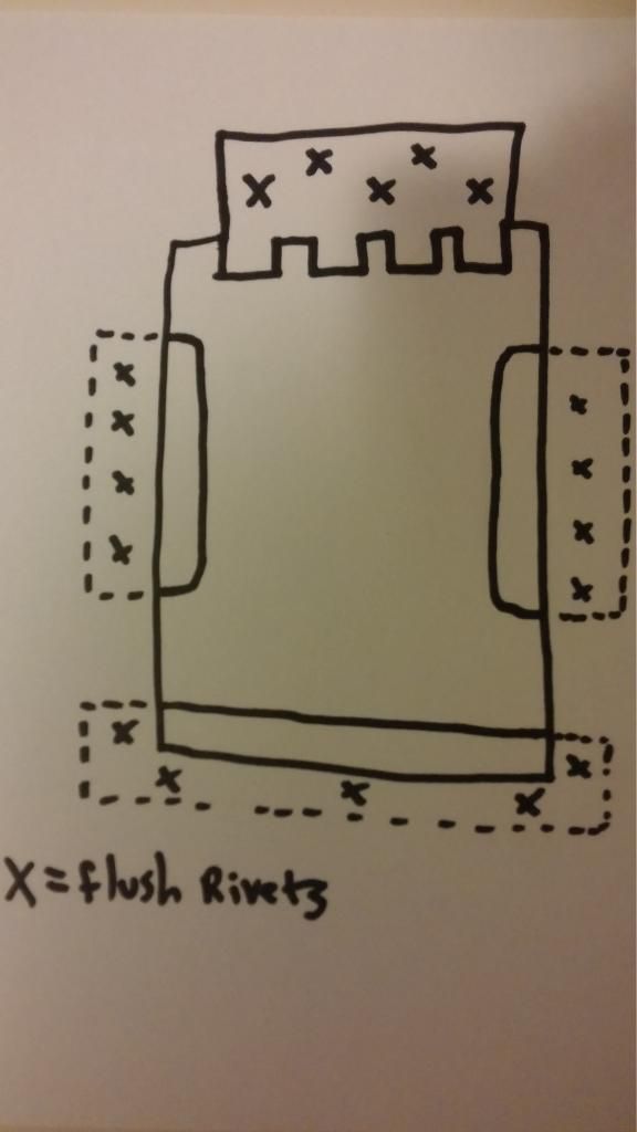
Drove down to Orlando and passed the tech and general today. Had a little time to work on the box. After some experimentation I decided I liked the radio better on the right side, and mounted it accordingly. Here is a shot of the top plate with 281a radio mount and new power hole for same. 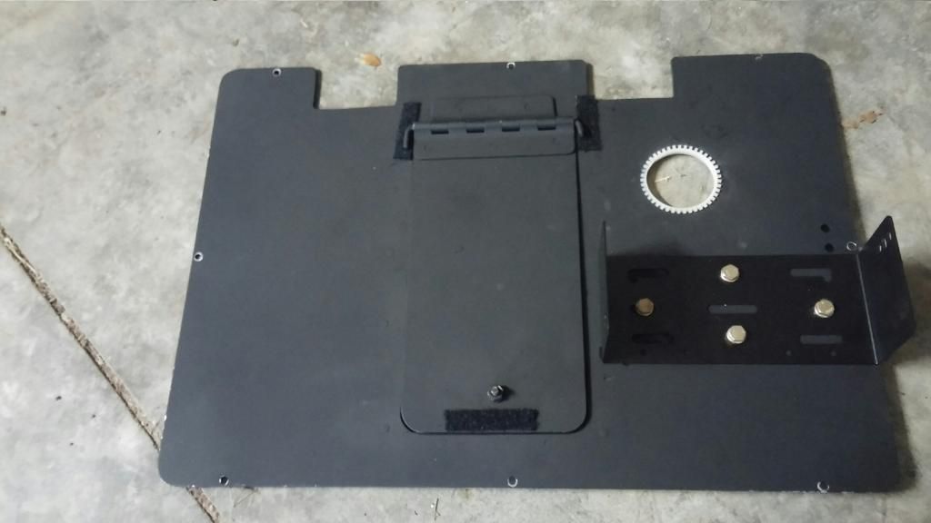
Here is a shot showing the case holding everything for travel. Velcro as per usual. You can see the logbook, notebook, pens and pencils, LED light, microphone, slimjim, and radio quick reference card all attached to the velcro field. Also routed the AC cord out the left hole. 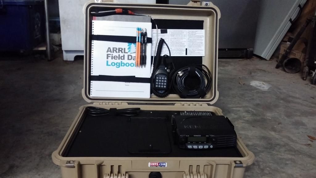
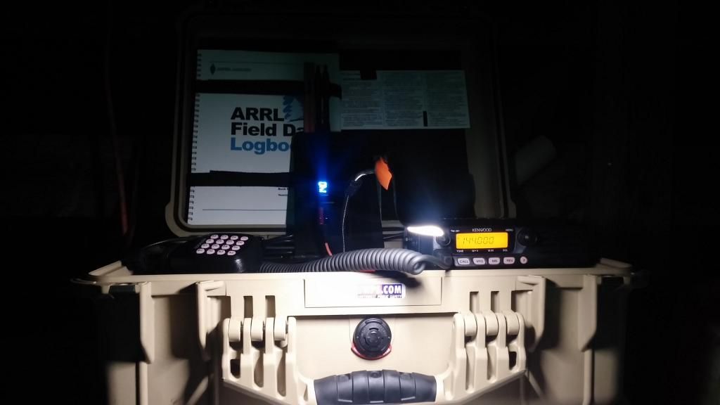
I will get some pics of it set up and running this weekend hopefully. Here's a quick shot of my first power on, going to try some receiving. 
More to come |
|
|
|
[#1]
MATERIALS LIST-- Updated as necessary
This is what I used to build mine. If you are new like me and you want a comprehensive list of what you need to get started, this will be such a list. I have read lots of reviews and received a lot of advice, and these components are all generally well regarded. I am going 2m only at the moment and adding an HF radio later. You can substitute any radio up to 100w transmit for the Kenwood 281a that I will be using. I ordered most of this from Universal Radio and Gigaparts, and will post my prices as of August/September 2014. You can use this to help estimate the cost of your own EMCOM box build. Be sure to shop around, even Amazon has some of this stuff. List Begins ***CASE *Pelican 1520 $120 *Pelican 1520 panel mount $20 ***RADIOS *Kenwood TM281A $125 *Kenwood 480 Sat (to be added later, not purchased at this time) ***GUTS *Samlex SEC1223BBM Power Supply with Battery Charger $130 *West Mountain Rigrunner 4004USB $76 *Universal DVM inline voltmeter $20 *10ga zip wire $0.90/ft (around 6-8 feet would be plenty, I ordered 30 just to have it.) *45a Powerpoles (12ea) $18 *Powercrimp tool $40 ***ANTENNAS *Slim Jim 2m antenna $25 *Hustler CGT144 $53 *Hustler MKR-2 Radial kit $22 (the Hustler will be mounted on a pole or tripod, the Slim Jim is for field/hasty use) ***MISC --Some of these things I already had laying around, and a price will not be listed. *Industrial Velcro *Wire Strippers *Screwdrivers *Fuse Multi Pack $9 *Inline Fuse assy. $7 *USB light $9 *Electrical Tape *Screws for panel mount 6/32×1/4 *Zip Ties *MFJ107b Clock $13 *5/8 Velcro cable wrap ***TOP AND BASE PLATES 17.5" x 12.25" with 5/16 corner radius. This will fit in the bottom without cutting into the sides of the case, and be tight enough that with a little velcro on the bottom it will not come out. I used the same dimensions for the top piece, and simply flipped the panel mount ring upside down. This makes a dished area that fits the described plate EXACTLY. I used CA glue on the brass inserts installed in the plastic panel mount ring. I made mine from metal because that's what I do. You can use wood or HDPE cutting board or whatever. The dimensions listed will still apply. Flipping the panel mount ring upside down also gives you another 3/8" or so of clearance between the top panel and the closed lid. The panel mount screws to the Pelican case and you don't want to be putting it in and removing it any more than you have to. Be sure you have the bottom plate rigged up the way you want it before installing the ring, the plate can't fit back out through it. If you use wood or plastic consider making some kind of porthole big enough to get your hand inside of the top plate. |
|
|
|
[#2]
This is gonna be nice!
|
|
|
|
[#3]
Will be watching this build.
|
|
|
|
[#4]
Posts updated, thanks for the interest. Hopefully this will be helpful for other new people.
|
|
|
|
[#5]
Looks good.
Keep us up to date as it progresses! |
|
|
|
[#6]
This won't work. Go ahead and ship it to me for disposal.
 lookin good. lookin good.
|
|
|
|
[#7]
Very nice, verticalgain! I like the panel mount for the pelican case (didn't know about those until recently) and the use of velcro. The inline digital volt meter is a nice touch also.
Looking forward to how this progresses. |
|
|
|
[#8]
Looking great
Just FYI, that perimeter insert is upside down and the thread inserts are designed to function with tension in the other direction. |
|
|
|
[#9]
Quoted:
Looking great Just FYI, that perimeter insert is upside down and the thread inserts are designed to function with tension in the other direction. Yes, it is upside down on purpose for the additional clearance. The inserts are also glued into the holes to prevent them backing out. These fasteners really only come into play with the case upside down. With the case on its side the top plate fits the ring so securely it bears the weight around its perimeter and not on the screws. Even shaking it upside down and trying to force the inserts out by hand had no effect. |
|
|
|
[#10]
Updated with more pics in OP.
|
|
|
|
[#11]
It looks great. My only concern is that the power supply doesn't have enough ventilation to prevent overheating.
|
|
|
|
[#12]
Quoted:
It looks great. My only concern is that the power supply doesn't have enough ventilation to prevent overheating. I ran it for an hour or two last night, just receiving on the NOAA channel and learning the radio interface. Had the door open so I could use the LED light, and the fan on the PS never kicked on, or got warm to the touch. Once I start transmitting I know it will develop more heat, if it winds up being more than the PS is able to handle I will add a computer fan to exhaust some more heat. Going to be busy a few days, hopefully I can get a daylight shot of it setup some time this weekend. |
|
|
|
[#13]
Quoted: I ran it for an hour or two last night, just receiving on the NOAA channel and learning the radio interface. Had the door open so I could use the LED light, and the fan on the PS never kicked on, or got warm to the touch. Once I start transmitting I know it will develop more heat, if it winds up being more than the PS is able to handle I will add a computer fan to exhaust some more heat. Going to be busy a few days, hopefully I can get a daylight shot of it setup some time this weekend. Quoted: Quoted: It looks great. My only concern is that the power supply doesn't have enough ventilation to prevent overheating. I ran it for an hour or two last night, just receiving on the NOAA channel and learning the radio interface. Had the door open so I could use the LED light, and the fan on the PS never kicked on, or got warm to the touch. Once I start transmitting I know it will develop more heat, if it winds up being more than the PS is able to handle I will add a computer fan to exhaust some more heat. Going to be busy a few days, hopefully I can get a daylight shot of it setup some time this weekend. In that case, carry on.
|
|
|
|
[#14]
I like your design of your Go Box!! Nice clean design and the LED light would sure come in handy in the dark.
I too have a TM-281a and was concerned on the power draw when transmitting from battery. The radio is "Low Power" 25W or "High Power" 65W which is a 14A draw max. Some of the other 2M only radios options allow for a lower wattage transmission settings, in theory, allowing for longer duration of from battery only operations. I plan to just run my TM-281a as a vehicle mounted radio. |
|
|
|
[#15]
Quoted:
I like your design of your Go Box!! Nice clean design and the LED light would sure come in handy in the dark. I too have a TM-281a and was concerned on the power draw when transmitting from battery. The radio is "Low Power" 25W or "High Power" 65W which is a 14A draw max. Some of the other 2M only radios options allow for a lower wattage transmission settings, in theory, allowing for longer duration of from battery only operations. I plan to just run my TM-281a as a vehicle mounted radio. I was originally planning on placing a small battery inside the case but decided to go with an external battery in its own box so I can get a longer runtime. I am still researching batteries, but will probably wind up with a group 24 AGM. I haven't been issued a call yet, so I haven't tried transmitting, but I am hoping the 25w setting will work to reach the local repeaters. It would certainly extend the battery life. I have enough wire and Powerpoles left over that I am also going to rig up a lead to my truck battery so I can plug into it as well. |
|
|
|
[#16]
[outlawbehavior]
I'd key the repeater. If it IDs/kerchunks then my gear works. [/outlawbehavior] |
|
|
 Win a FREE Membership!
Sign up for the ARFCOM weekly newsletter and be entered to win a free ARFCOM membership. One new winner* is announced every week!
You will receive an email every Friday morning featuring the latest chatter from the hottest topics, breaking news surrounding legislation, as well as exclusive deals only available to ARFCOM email subscribers.

AR15.COM is the world's largest firearm community and is a gathering place for firearm enthusiasts of all types.
From hunters and military members, to competition shooters and general firearm enthusiasts, we welcome anyone who values and respects the way of the firearm.

Subscribe to our monthly Newsletter to receive firearm news, product discounts from your favorite Industry Partners, and more.
Copyright © 1996-2024 AR15.COM LLC. All Rights Reserved.
Any use of this content without express written consent is prohibited.
AR15.Com reserves the right to overwrite or replace any affiliate, commercial, or monetizable links, posted by users, with our own.