|
[#1]
Quoted:
So when you say optimize it for 500MC how will that effect the performance at 144MC? Also when is the group buy for the kit going to be ready? My WxSat station needs moar ears. Good question deserves a long answer. The preamp here is a relatively narrow band [but quite broad, maybe 20 MHz wide until noise figure degrades on each side of center] Vs. the wide band preamps you see, most now using the monolithic amplifiers IC's. Some of these like the Mini-Circuits broadband preamp that goes from 50 to 2 Ghz or so with a GREAT NF of about .75 dB are well suited general antenna amps if nearby signals aren't too strong. The wideband preamps amplify everything coming off the antenna and can create overloading issues in your receiver. The narrow band ones like the one I designed have a little bit of rejection to signals not far from their center frequency, increasing as you get further from center. Some of the wideband amps like the Minicircuits new monolithic amp require a lot of juice to bias, as much as a 1/10 of an amp. They will run on less and not meet published specs. Some make do with a lot less. The narrowband preamp like here as I have described above will run nicely on 500 MICROAMPS it was surprising to find out. As far as a group build, I'm waiting for someone to volunteer to coordinate it too. 
What are you using for the receiver and antenna for your WX station?? |
|
|
|
[#2]
I think I'll design a board for the fancy MiniCircuits high power wideband low noise chip to go along with the present one.
|
|
|
|
[#3]
Here's an excerpt from an article I found on Repeater Builders' site including the relationship of 'noise figure' improvement to real would commo performance.
An important point when trying to receive weak signals. Quote: Roger Grady, K9OPO, offers one more significant fact on the subject: The quieting curve of an FM receiver is very non-linear. 3 dB will make a very noticeable difference if the signal is well into the noise, barely any or none at all if it's strong. The result is that a 3 db improvement will in most cases approximately double your range. In closing I would agree 3 dB is not noticeable or barely noticeable if the signal is already well out of the noise. However, in areas where you are trying to push repeater coverage from a given site to the limits, 3 dB is significant on the outer fringes and in the problem areas. I say this from personal experience; I have seen a 3 dB change in repeater power or antenna gain make a significant and consistent improvement in fringe/weak areas. It can be enough to make the difference between the repeater being usable or not... I call that significant. Article ************************* Put another way, since the threshold of a signal's intelligibility is only a couple dB out of the noise, ---just a few dB increase in received signal strength [due to an increase in transmitted power, a better antenna, or an improvement of the receiver's noise figure, can make the difference in getting a message thru. Boiled down, a surprising little improvement of received signal at the threshold of intelligibility, can make the difference in copy or no copy. While making the performance measurements on the amplifiers above, I saw that effect but didn't tie what I saw together in a way, to articulate it the way the author does. |
|
|
|
[#4]
Worked with the 440 MHz preamp for an hour or so today looking at ways to match the 50 ohm input to the FET.
The simplest was the best so far, a 50 ohm line to the drain with a tiny 8 pf ceramic capacitor in series. The input inductor is a hairpin loop, roughly 3/8" in dia. Results: The R7000 has a good sensitivity of 12 dB SINAD of ~.25 uv. With the preamp ---so far, not optimized yet I'm sure, the sensitivity is .16 uv. That's about a 5 dB improvement in NF. Significant. |
|
|
|
[#5]
Today, I changed the input circuit and got down to a sensitivity of .11uv at 440 mhz.
The R7000 is quite good at 440 MHz and with the preamp, the NF is improved by about 8 dB. This is about as good performance that most systems might need, before going into far more exotic amplifiers, I think. I have found multiple solutions to stability issues to maintain consistent NF as well as simple techniques any experimenter can use without a spectrum analyzer to evaluate the stability of his preamplifier. The transistors I've been using recently are ATF35143 ----having the smallest gate width [400 u] of that series and most prone to instability. It's remarkable that they are so stable in this 440 MHz circuit. ATF35143 DATA SHEET |
|
|
|
[#6]
This preamp building thing has bitten me.
So yesterday I dug out an old noise source I got at a hamfest years ago that was rated for the ghz range. And an HP 8970B Noise Figure Meter I've had around and never used in my biz thinking someday I would find a use for it and good noise source to go with it, but never did. Noise sources look like this: Mine that I took apart looks sorta like the one in the middle. New they cost about as much as a good used car. Like this purty one from HP.... 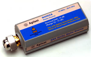
Here's a discussion that takes a LITTLE of the mystery out of them... Building a noise source and discussion The old noise source I had was spec'd for abt 16 ghz and not below 15 ghz. Obviously that wasn't going to work with VHF and UHF preamps. So thinking a bit, I wondered what abt it made it so special to limit it's output to so high a freq range. I had nothing to lose and I took it apart. Inside I found a gold plated machined housing and an attenuator connected with precision SMA's marked 13 db made by Narda, not the mfgr of the noise source, and that the atten had been obviously modified. I put it on the 8510C and swept it and found it was mod'ed to roll off [increase atten] as frequency increased. [So, the 2 variables together combined, to flatten the sources' frequency response in the spec'd band] Hmmmmm..... Nothing to lose.... So I took the gold plated capsule containing the business part of the noise source to the mill and cut it open. Well what did you expect???? Under magnification, I could see a bonding wire abt 1/6 inch long shunting the noise diode to ground, and acting as a high pass filter limiting the sources output to the high ghz range and shorting out low frequency noise. So you know what I did, I took tweezers and removed it.
Then I replaced the 13dB atten at the output with one of about 15 dB that is pretty much the industry std I have read. Therefore I should have made a good noise source and save mega bucks in the process. It turns out I did. I hooked it to the 8970B and after a big learning curve figgered out how to make the instrument work. Here's HP's brochure on their noise figger meter.... 8970B brochure and discussion And a pix with a noise source being cal'd on the right side.. Not mine.... 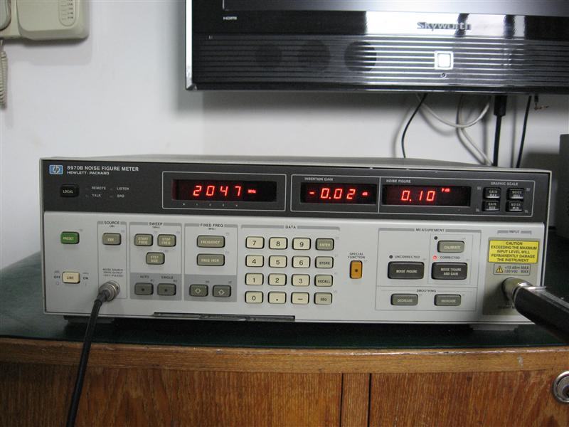
And a video... NFM Brief theory of NF measurements -that I have yet to comprehend... NFmeasurements Oh my goodness. This is like living next to a perfect woman for 10 years and never giving her a glance, until one day -you find out you're both in love w/ each other. [Not that my 8970B gives a rat's behind abt me....] So, reading thru the op manual, that is like a mystery manual, I finally got the system working with the ARR and my EXPY preamps. WOW! Is all I can say..... The covers were off the preamps and if you have been following this topic you know I have the fluorescent lights from Hell in the ceiling. I turned them off and the noise figger displayed matched what I expected, about .4 dB. the 450 MHz preamp was a little better than the 150 MHz one. I'm stunned and have to stop and think abt this while I do some other work, but I must say that much progress has been made toward quantifying the performance of various amplifiers I'll make, I don't know what to do next, this is all so new to me.... I wanted to do this for so many years... |
|
|
|
[#7]
EXPY37,
Great thread: even if I don't understand exactly how the magic happens here, I very much understand the practical implications. I'm interested in a group build if one forms. |
|
|
|
[#8]
Ha! I never understand a thing he says in these threads, but I read them anyway because they're fun to read and I can tell Expy is having great fun doing... something.....
Good luck and thanks for sharing Expy! |
|
|
|
[#9]
Thanks folks! Yep Variable, it doesn't matter what you do as long as you do something, the direction will become clearer from there... [You remember I see...
I've sort of figured out how to use the HP8970B's and have calibrated the AIL noise source I found in my hamfest stuff from years ago. {I know I must have saved it for some reason Learning to use NFM's has been quite interesting -and time consuming! They have a quite extensive capability and were the gold standard of NFM's until more recently when Agilent came out with a new line of instruments that do a lot more, and with an internal display. Very nice equipment. Agilent's new noise figure meters, go to 26 ghz IIRC, and the noise sources have built in correction tables and temperature compensation, but for all practical purposes, at $15k, the utility for doing the sorts of tests we're talking abt here, there isn't much difference in measurements of the 8970B. ETA-- $15k??? Oh wait, try starting at $30k for a 3ghz range and up to ~$75k for a range to 26 ghz in one beautiful box... Agilent's 3 current NFM's Compare them I don't know if there were instruments bridging the above linked ones in the years between the HP8970's and the latest. In the HP 2001 catalog, there is an N8973A that went to 1500 MHz [lower than the various 8970B's, basic or with options, and it appears it wasn't a big seller. It looks like the current models with the internal display. It isn't in the 2000 catalog. The displays in the new analyzers show 2 traces, noise figure and DUT gain, at a glance, just like a spectrum or network analyzer presents their info. [The 8970A meters came out in the 1980's and much engineering was done to update/improve them in the 8970B models in the 1990's. They remained the workhorse of RF noise measurement until the 2000's and still are extensively used today] Here's a link to a collection of Google pix of the various HP NFM's and Noise Analyzers [internal display] over the years. NFM's The 450 mhz EXPY preamp in the Altoid can outperformed the AAR preamp by about 1/10 to 2/10 dB. I expect the poor input circuit mechanical layout is attributable for the difference at 450 mhz. The 'ground' path from the connector to the PCB is not direct but goes thru longish standoffs so a lot more inductance in comparison. The Altoid preamp at 150 MHz is about the same noise figure as the AAR for all practical purposes as would be expected, and for some reason, the NF tested about 1/10 dB poorer than the 450 ones. I think external RF is somehow getting into the DUT [device under test]. The 450 preamps were insensitive to the ceiling lights from Hell in my shack vs the 150 MHz preamps. I can take the NFM to the mountain and test there and be confident of a low RFI environment, and the equipment is not that bulky and heavy to take. I think the next step when I can schedule it is to re-lay out the preamp board optimized for the 2 respective frequencies and build up one of each 1750. I'll try to post pix of the test setup if anyone is interested. Unlike Agilent's latest NFM, the 8970 doesn't have a display. It has X, Y, Z, outputs on the rear panel to drive a plotter or video displays such as they were back in the day. I have an Owan digital scope I may bring down and hook to the NFM as a real-time display and see how it looks. |
|
|
|
[#10]
Found an alternative to the Krytox spray for enhancing the toner contrast of the negatives.
Walmart has a spray can of brake cleaner for ~$3 that contains acetone and toluene, just like the Krylon. |
|
|
|
[#11]
In this Oct QST, there's an article on dynamic range, discussion of dB levels, and on page 60, a few paragraphs about noise figure and noise temperature, as related to receiver front ends.
|
|
|
|
[#12]
Great article and a handy reference. I need to keep reading that stuff to keep it straight in my pointy little head.
And MOAR PREAMP PLZKTHX! I so want to build one, but have so much more to learn. |
|
|
|
[#13]
I'm with ya Blammo...do want preamp! |
|
|
|
[#14]
Got the AIL noise source mentioned above that I found in my junk/hamfest goodie box and modified to operate from 10 MHz and up, professionally calibrated and it came back with very nice specs, comparable to the fancy ones....
Cost to cal was less than $50. |
|
|
|
[#15]
Still waiting for mine.
|
|
|
|
[#16]
Quoted:
Still waiting for mine. Time to get busy and build one! |
|
|
|
[#17]
Anyone going to try this year?
|
|
|
|
[#18]
Getting ready to put one on a repeater...
|
|
|
|
[#19]
Abt ready to aut one on a repeater -still... And ran into this...
**********CONNECTOR ALERT*********** Noticed that BNC connectors on imported BNC jumper cables and antenna cables, some of the Male BNC's are CRAP. I've swept them on an Agilent network analyzer and they are intermittent and the SWR jumps all over the place. The reason is the contact 'strips' around the Teflon insulator are made of poor material [nprolly not beryllium copper] and aren't large enough in dia to make good slip contact with the INSIDE of the female barrel. A quick tool to make to check to see if you need to replace a potentially bad conx is to take a FEMALE BNC connector, carefully drill or press out the center pin and Teflon. Grind or file off the 2 bayonet pins. Then slip the BNC male in question into the female BNC and see how it grips. If loose, cut it off and throw it away. Recently bought some RG174 3 foot jumpers to use for testing on the bench and was getting all sorts of weird results. Swept them and all BNC's were bad. They weren't expensive so no big deal. Just ordered an NMO mag mount and checked the BNC and it was junk. Cut it off and now have to replace it. I like buying old US made conx on Ebay vs. the cheap imported conx, altho I buy those too, and some are decent quality. The higher the freq of the application the more significant the bad conx performance will be. |
|
|
|
[#20]
Today did an experiment with an AM aircraft band radio retuned to 2 M.
This is likely just as applicable to FM receivers. The original transistor is a 3SK85 Hitachi dual gate MosFET. I replaced it with a surface mount 3SK147 in a surface mt package 1.5 x 2 mm dimension. To replace, all that needs to be done is pull the original and mount the surface on on the backside of the board. The D, S, G1 and G2 all line up. Then retune the coils either side of the transistor. Performance improvement is dramatic. The old SK385 probably dates to the late 70's, and the new one from the late 80's. Even state of the art MosFET's don't have too much more to offer. Improvement was from getting a decent S/N signal [audio quality] at about 2 uV... With the 'new' xistor, 1/2 microvolt!!!! For a similar audio to noise quality. Translated to antenna performance, this is like getting about 7 or maybe 10 more dB gain from the antenna. |
|
|
|
[#21]
MosFet mod has had some issues.
They are blowing out occasionally presumably due to power up 'surges' where the low current 10 volt regulator doesn't regulate quickly enough. Plan on putting a zener at near the drain ckt. |
|
|
|
[#22]
Just designed a different way to easily make a VHF [or UHF] Yagi antenna and have it almost finished ready for pix...
|
|
|
|
[#23]
I don't know how I've missed this thread for eighteen months. Cool stuff! I'm going to have to put on my thinking glasses and get a beer and see if I can make sense of what you've got going on here.
|
|
|
|
[#24]
Good, I'm going to post a cool design for a VHF Yagi antenna easily made from Box-Store parts and am going to try to integrate the LN preamp into it.
Working on it right NOW |
|
|
|
[#25]
Tuning the Gamma Match on the VHF Yagi tonight...
Method of construction... One 10-24 stainless screw at each element location, plus the fitted hole the element goes thru, holds securely. 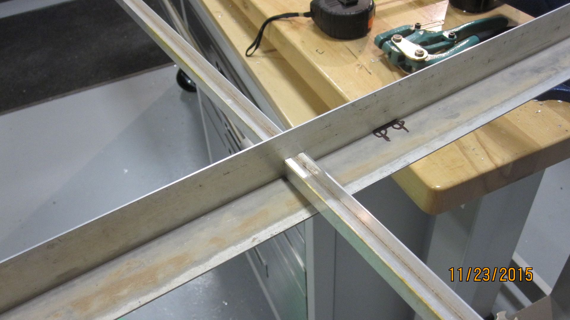
Preliminary testing... Not ideal RF wise... Get's better... Note Gamma Match optimizing method... 
This pix shows the preliminary way of using some coax and braid for the gamma match to quickly get in the ballpark for dimension and element tap point. Pretty squirrely construction... 
Incidentally, there's a handy [ATV] mounting plate available at Harbor Freight for under $5 IIRC. Going to use it to mount on the Yagi boom to mount it to a metal building wall. Fixed position. Hams can find all sort of uses for it since it has a right angle bend and lots of holes. It's easy to drill more if necessary. Thickness is just under a 1/4", stout... 
|
|
|
|
[#26]
Wow is all I can say!
|
|
|
|
[#27]
That is freaking slick, Expy!
|
|
|
|
[#28]
Lot's of hams build these antennas and use a Gamma Match to couple the 50 ohm feed line to them
Alternatively 75 ohm coax in a balun config can be used but it can be a little awkward for a VHF and higher frequency antenna. [ETA, there's some 75 ohm -I think- mini-coax with F conx on it to hook up components for indoor TV, etc. that might solve the awkwardness of larger 75 ohm coax and will probably work to 50 watts or better at 150 MHz] The Gamma Match is made up of a center conductor soldered to the connector for the feed line, a 'dielectric'/insulator and an outer conductor, like braid or tubing that connects to a 'tap' point to the driven element. I had some trouble improvising the gamma match using hobby store and junkbox stuff and found another way. [Some folks used a large coax like RG-8 or 214 and took the inner dielectric and center conductor and used that. The issue is it's hard to slide the PE dielectric back and forth on the center conductor to tune. So, I took some dielectric and center conductor from LMR400 coax, abt 10 inches, put it in a dish with household lye for a few days to dissolve the aluminum foil that's 'bonded' to the foam dielectric. It helps to sand the foil so the lye can eat it away faster and to put the dish in a warm place to speed up the painfully slow reaction. Once you get the center conductor with the insulation on it, some hobby shop brass tubing that slips neatly over it works great! There are a lot of Yagi calculators on the net to help get element dimensions close and even an interesting Gamma match calculator, that helped a lot, and I'm still trying to figure out.
Digital SWR meters with a display are so plentiful nowadays, as already mentioned in the folded dipole Yagi thread, they make tuning a snap. Last night I got an SWR of about 1.5 over a 4 MHz bandwidth at 150 MHz. That's inside a building with a lot of reflections. Today I'm going to set it in the overhead door area and point it outside just to confirm the adjustment, then finalize the match construction. The U-channel is hardware store material, there's inexpensive aluminum extrusions in the carpet departments, old picnic furniture and similar stuff can be a source for elements and boom. Old TV antennas are a great source, if you can find them, don't overlook thrift stores for items that aluminum extrusions can be sourced. Harbor Freight has tall 'jack stands' that go to 6 or 7 feet, on sale from time to time and with coupons, make a fast heavy stand to put an antenna on outside for testing or even 'permanently' These are plenty heavy and won't blow over... 
|
|
|
|
[#29]
Thanks for the encouragement guys!
Took the antenna mounted to the stand above, and pointed it outside last night and the VSWR dropped lower! Did I say heavy? Also, I'm wondering about making a gamma match using a brass or aluminum tube that fits the OD of some RG-8 or 214 coax, using the black PE plastic jacket as the dielectric and the copper braid as the inner conductor --for the capacitor part of the match. Wouldn't be able to slide to adj, but once the dimensions are found, would be easily reproducible... The capacitance of the coax is easily measured using one of the $15 LCR digital meters from ebay. The aluminum angle the elements are mounted to is likely the thinnest wall thickness available
...and is a little noodlely I'm going to go with it for the moment and mount it as soon as the wx and getting to the barn allows. The angle at the box stores is a heavier wall... |
|
|
|
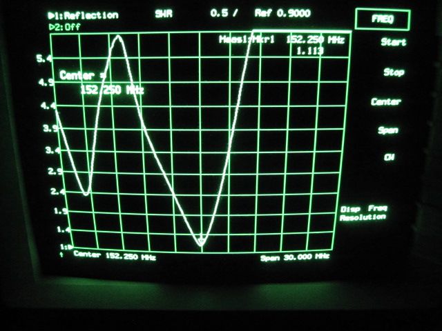
[#30]
Return loss of antenna at 152 MHz high end, have better pix at 142 MHz lower end, with a different network analyzer, SO needs to upload them...
Easily tuned, need to make a better Gamma Match clamp... So much to do... 
|
|
|
|
[#31]
Quoted:
Found an alternative to the Krytox spray for enhancing the toner contrast of the negatives. Walmart has a spray can of brake cleaner for ~$3 that contains acetone and toluene, just like the Krylon. Ran into some issues... First- Been making a lot of boards... This means a lot of positive transparences for the board revisions My SO helps set up the etching stuff and we can make a new revision bd in an hour and she cleans up and puts stuff away... The bds are mostly SMD components and some of the stuff is very fine needing good resolution The vacuum UV exposure unit we bought off eBay and rebuilt has made a HUUUUGE difference in the resolution of the bds.
Enhancing the Toner contrast with the Krylon spray on the shoebox lid technique - hasn't been working as well as it used to for some reason... The contrast just isn't there... I went back to the Toluene [any hardware store] in the bottom of a glass dish with a cover and the film inside and it works good again. To avoid having to cut the film before 'enhancing' contrast, I found simply laying the film over the top of a rectangular 6 by 10 inch or so Pyrex dish... Important -emulsion side DOWN Then covering it with a shoe box top and a small weight works fine... 'Developing' the toner in Toluene for 8 minutes is fine in a cold room. I just did one and the result is almost total opaqueness... Actually I did about 20 transparencies trying all sort of printer combinations... This can get expensive unless you shop on ebay for cheap material... |
|
|
|
[#32]
It's important to keep the transparency printer clean and free of dust and oils that may be aerosolized and floating in the air.
My SO uses an orange Home-Depot stretchy bag to cover the dedicated printer. It's in the shop area -maybe it ought to be brought into the lab... |
|
|
|
[#33]
Wonderful idea in the May issue of QST on page 63 for assembling/clamping 'Tape Measure Elements' into antennas...
The tapes are sort of difficult to drill to put screws thru neatly... WB0SVS suggests clamping tape lengths in, say, a PVC plumbing cross using a smaller dia 'nipple' of pipe to insert in the same hole to lock the tape in place... This idea allows for a fast assembly of various antennas... Also, regarding the Yagi antenna above... Haven't done anything with it because of laziness and I can't put it up even if it were finished... This said, using the 1/16" wall aluminum angle causes the Yagi be all noodly, twisty, and squishy, and psychologically has really been bugging me not to want to have anything to do with it... I didn't want to spend the ridiculous $20 or so on a 1/8 wall stiff al angle from the box store, but the other day I asked my SO to pick up a piece of 1 1/2" x 1/8" wall material
So, one of the first thing's I'm going to do is replace the weak assed stuff with this new angle. The Gamma match works real good and I need to figure out how to make the solder conx between the Gamma match center conductor and the N connector so it doesn't crack over the years. The stiffer angle will help a lot... Maybe a piece of PCB can be used some way to make a robust connection... This raises anther idea I haven't seen done... How about a Gamma match where the capacitor assembly is made from a piece of PCB material rather than concentric tubing, dielectric and center conductor??? |
|
|
|
[#34]
Want to add, I measured the capacity of the concentric gamma match outer tube and center rod with foam poly dielectric like used in LMR400 coax, and the required capacitance at 150 MHz is ~12 pf...
The tap point of the end of the Gamma match tubing seems to be best at about 5 inches from the cold [ground] end of one side of the dipole... I don't see why this can't be duplicated with PCB material and coated for Wx resistance... |
|
|
|
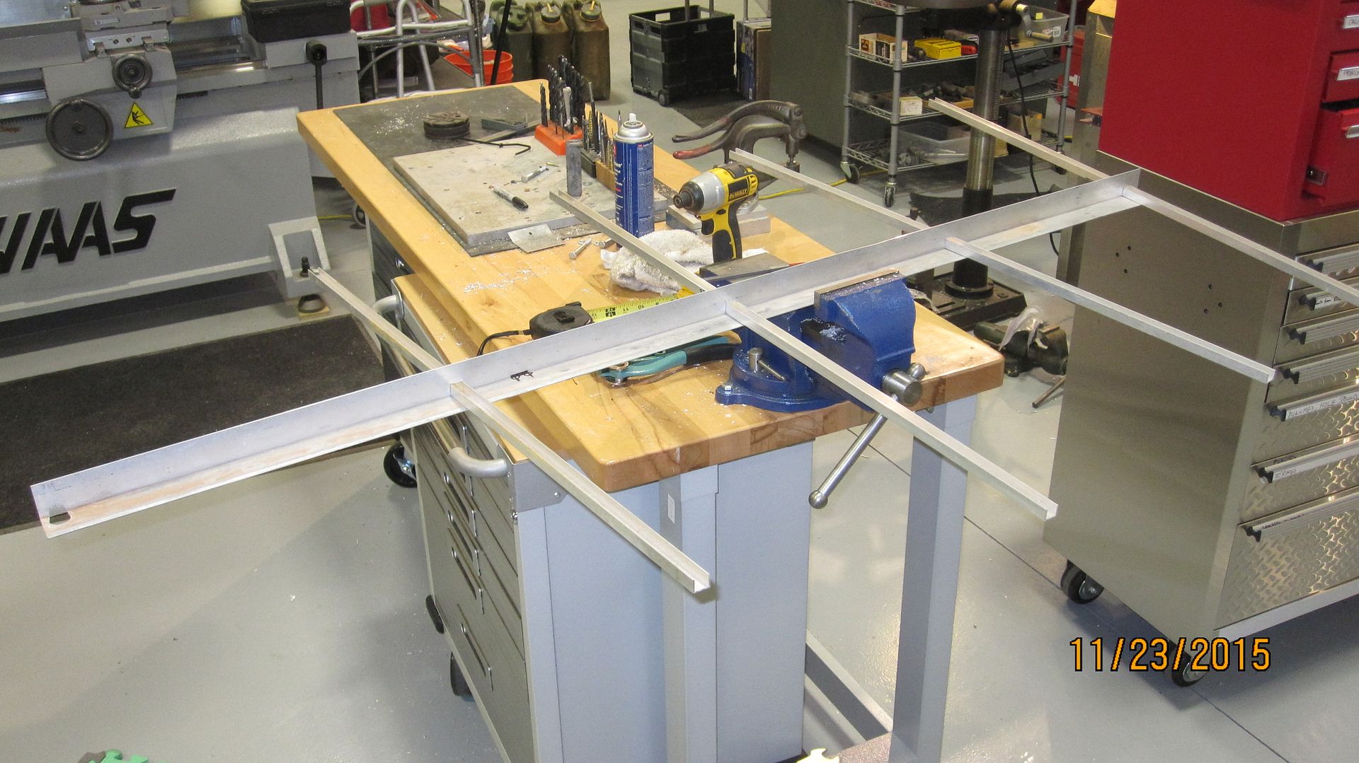
[#35]
I'll admit to have been frustrated with this VHF Yagi antenna project, partly because of the 'noodly' 'boom' because the angle aluminum is too thin for 4 elements ---and that was easily solved...
But more so because of the 'technical non-elegance' of the Gamma match. That too has been solved. The antenna is ready to mount and has excellent performance First some pictures that led up to finishing it ---and some hints, tips and ideas that will hopefully be of value to others. First picture shows the revised Gamma match. A Gamma match uses a series capacitor connected to the 50 ohm [in this case] feed line [coax] and matches that impedance to a tap point onto one of the dipole driven element halves. I've designed this Yagi to work from the 2 meter band to the VHF public service bands, and have tuned it to a rough midpoint of 152 MHz Only minor adjustments are needed to tune it to 146 MHz or 156 MHz, for example, including the lengthening of the elements and adjusting the Gamma match. Additional elements can be added and dimension calculations are all over the net. Gamma match issues Instead of using the center dielectric and conductor of some RG-8 or LMR400 that's hard to re-adjust, for the capacitor [8 to 15 pf]... I looked for some item readily available that had the right ID and OD for the outside brass tubing and a tuberculin syringe, with it's inside dia reamed with a number 10 drill to fit hobby shop brass tubing or rod in the correct diameter of about .193 [the KS brass display] slides in nice with a bit of friction. The syringe needs the outlet end trimmed off -leave the flange as it has a purpose. A mini-alligator clip can secure it to the terminal lug so it doesn't move when sliding the small rod in and out to adjust capacitance. The rod [I used tubing] slides thru a number 10 or 12 quality ring terminal lug with the ring hole enlarged with the same #10 drill bit. The syringe flange insulates the larger tubing from the terminal lug. A rubber band as shown, ensures the small tubing makes contact with the lug so it's easy to measure SWR or return loss with whatever instrument you have to tune with. The connector is a type N with a contact pin similar to an SMA ---I had these in stock, most any connector can be used. I used some brass tubing to make a poor fitting bushing and soldered it, the terminal, and the connector together. The larger brass tube is the other half of the Gamma match capacitor and it is connected to the driven element with a strap of aluminum formed to clip to the tubing and get clamped with a PLASTIC clamp to the element. 
Continuing |
|
|
|
[#36]
This arrangement was sort of easy to adjust for a good match.
The old brass tube and dielectric center conductor is on top of the analyzer. The bandwidth is about 5 MHz and this antenna has only 3 elements, I cut the 4th one off because it was too wiggly with the thin boom material I used. Incidentally, there's a couple of inexpensive capacitance meters on ebay for abt $30 that will measure the required ~10 pf capacitance required if used carefully. 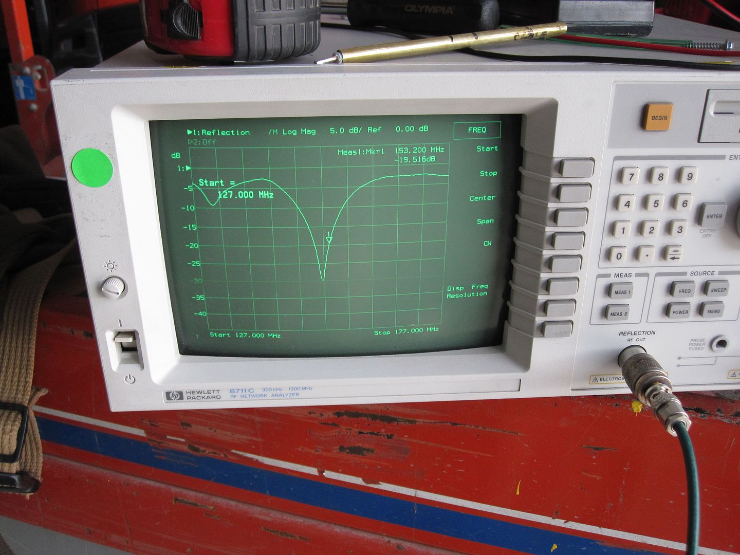
Continuing |
|
|
|
[#37]
Here's the test setup a few days ago --it gets better later---
The screws are out of the reflector and director elements so I could play around with their lengths and position on the boom. Turned out the position was OK, the reflector and director element lengths did get changed and that helped a bit. Return loss is excellent in the final config. 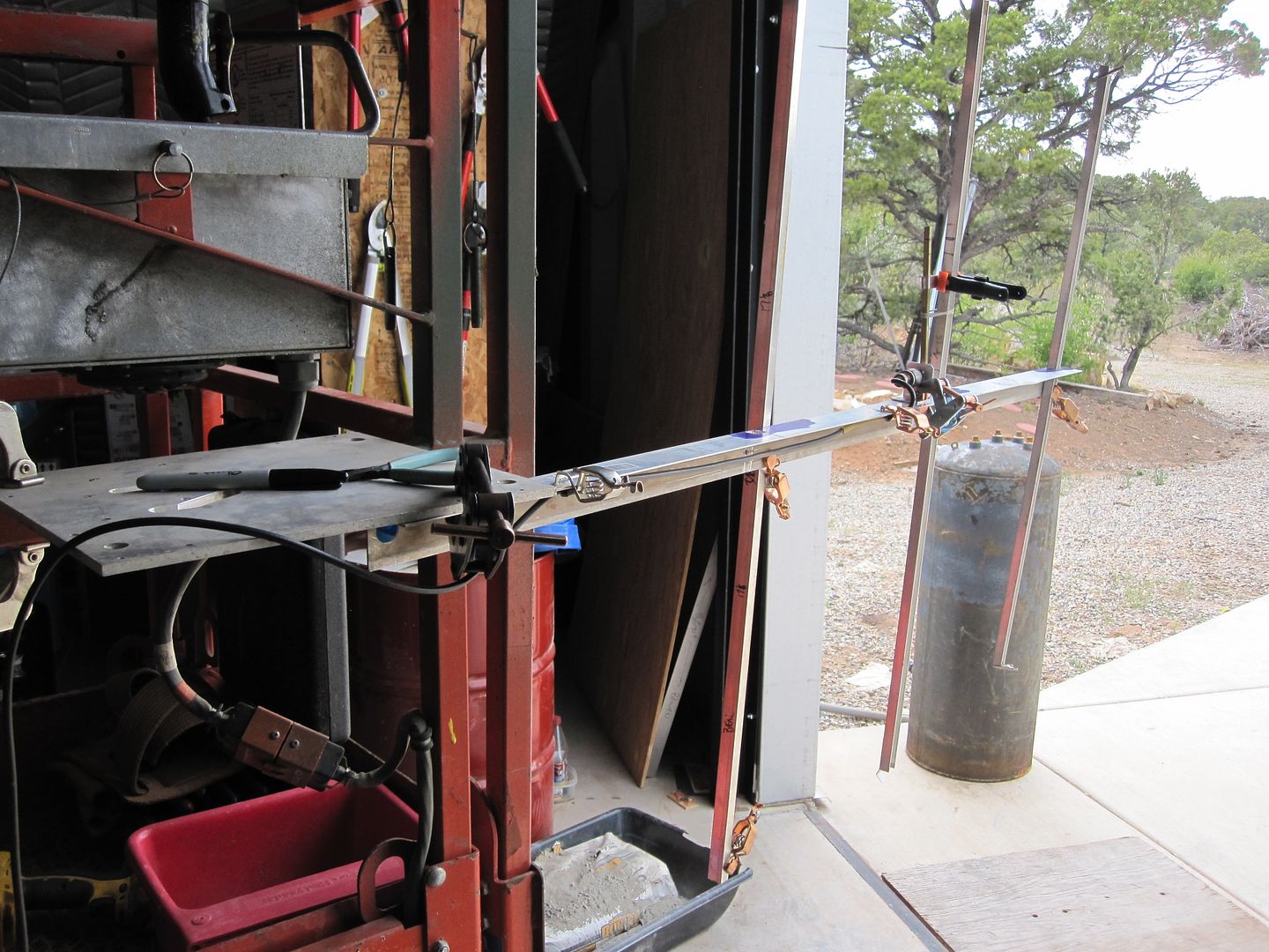
Here's some of the individual components to help illustrate how the Gamma match is assembled. The original capacitor is above the new one using the syringe as a dielectric. The yellow sleeve of the lug is pulled off and the scale on the syringe is useful 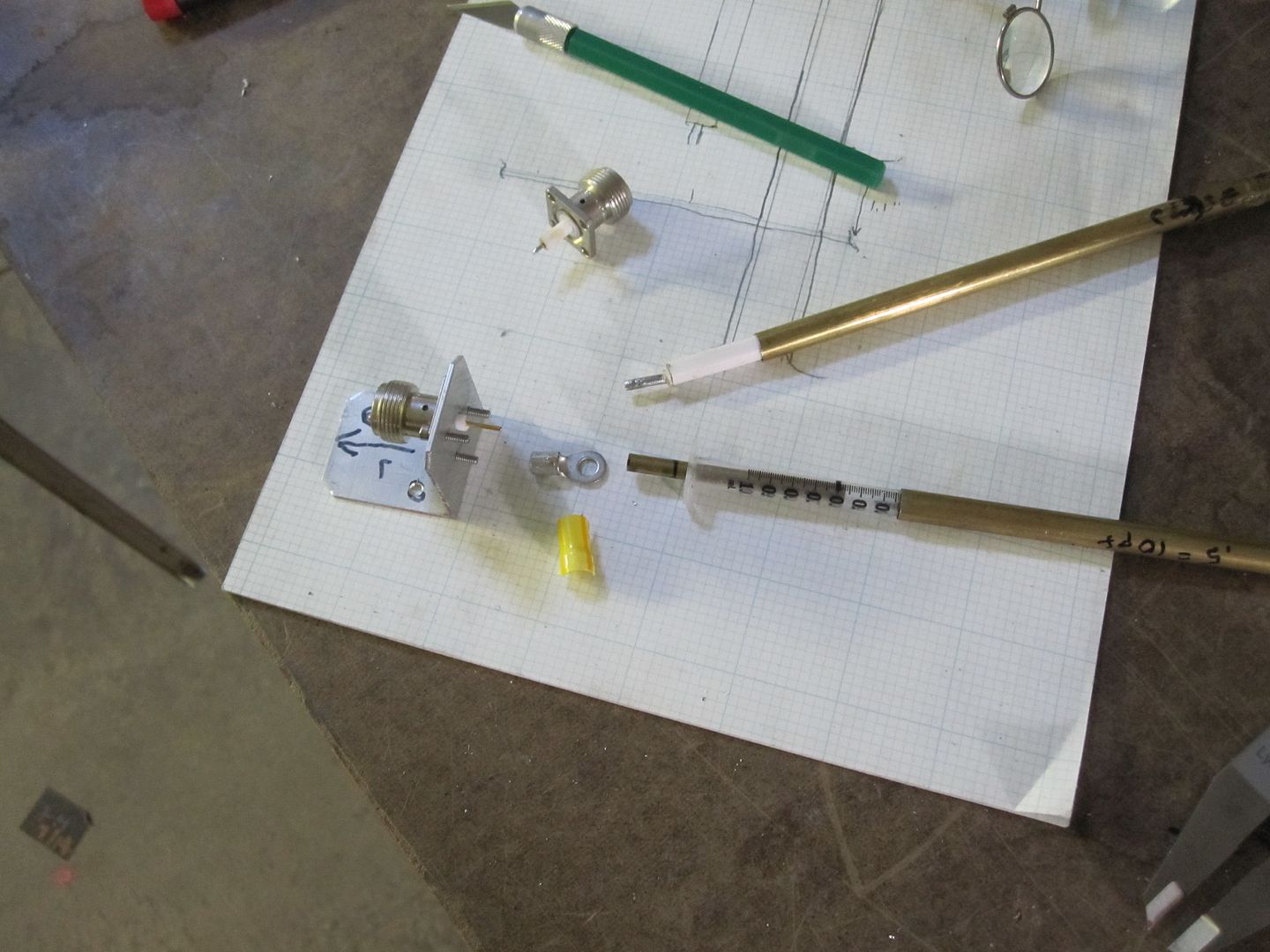
Continuing... |
|
|
|
[#38]
Another pix showing more parts and the connector bracket, mtg screws, etc.
3-48 screws mounted the connector to the bracket, all the stuff is at a hobby shop or cheaper on eBay. 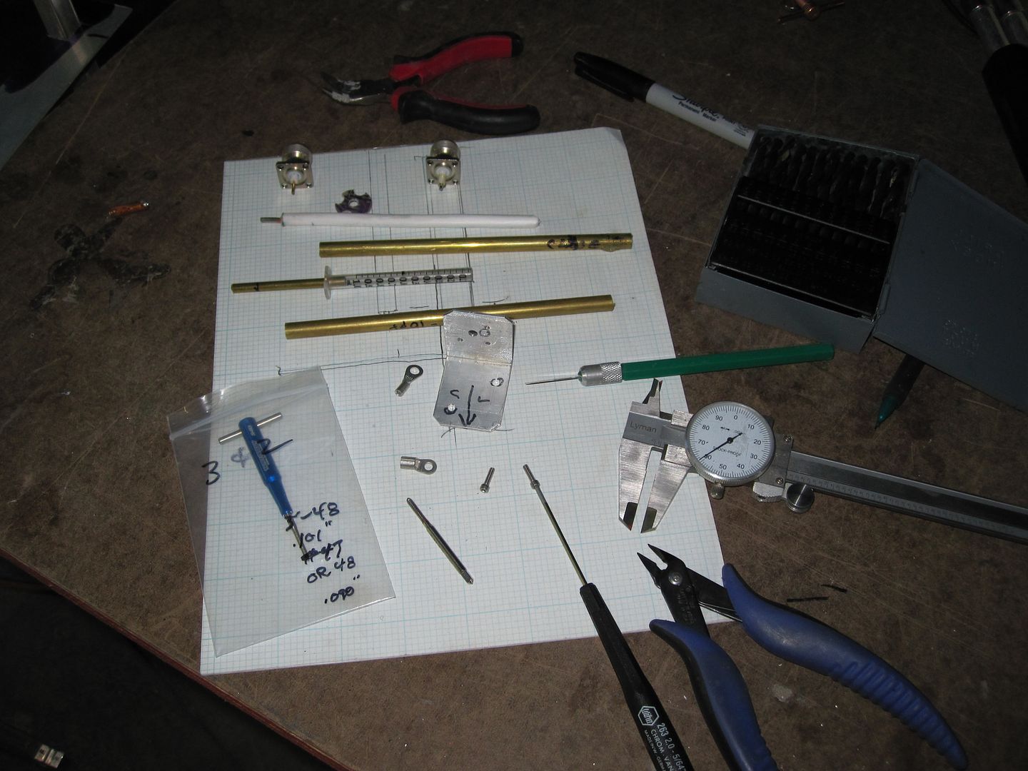
|
|
|
|
[#39]
Held the connector in a vice and spotted the center of the holes to be tapped with a drill that fit the ID of the connecter mtg holes.
Only a dimple, to center the tap size drill for 3-48 --then drilled those holes. 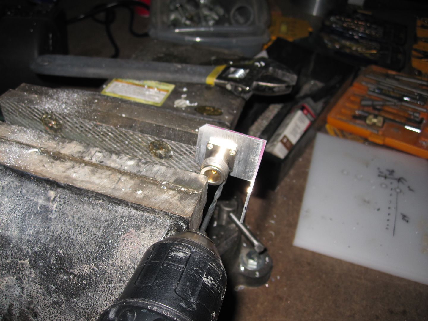
Next drilled and tapped the holes... I often use a cordless drill with the tap chucked and a lot of care. 2 or 3 holes is enough.. 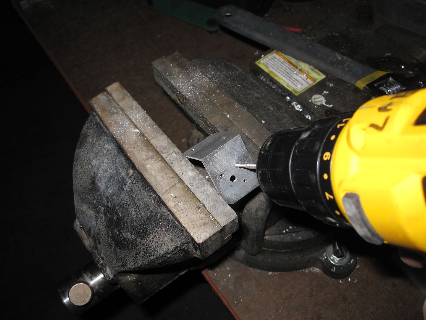
|
|
|
|
[#40]
Here's a GREAT tool from H-F or ebay, for ~$30, a mini cut-off saw with a very fine teeth that will precisely and squarely cut brass and al tubing, coax, etc.
Not ferrous material tho... Cutting the brass and other stuff accurately would have been an ordeal without it. 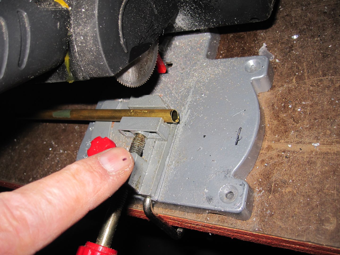
|
|
|
|
[#41]
Here's a trick to enlarge the hole in the first terminal, put a fitting drill bit in the end and then slowly drill out the center. Hold everything in a vice... Or you'll find out why...
See how the small and large tubing and syringe make the capacitor? In the next posts with pictures, I'll show further refinements and the final design. There's a BIG improvement to connect the large tube to the driven element --my SO needs to get me the pix... 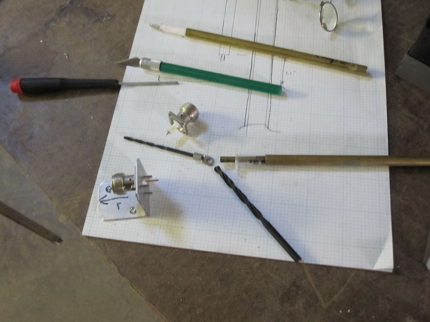
|
|
|
|
[#42]
Those spring loaded center punches make set marks super easy and can be picked up at HF.
I like the gama though it is coming together nice. |
|
|
|
[#43]
The spring ctr punches are real handy!
Mounted the Yagi on a TV tripod mount like this... 
Replaced the 2" short tube they sometimes come with -with a 1 5/8" conduit or chain link fence top rail, cut to about 6 feet. Mounted on the metal 'barn' roof yesterday and only had a minute to run a signal test with an Icom R7000 receiver. Picked up a digital continuous pager transmission from the direction the Yagi was pointed... I think--- The comparison antenna is a Radio Shack broadband conical antenna -those actually work very well and there's plenty on the market even after R-S went out of biz, by various mfgr's and prices. 
Thru about 70 feet of LMR400 the S meter on the R7000 showed a significant increase when switching between the Yagi and the R-S broadband. Didn't have time to measure the dB improvement but guess ~10 db... Will do that in a day or two. Still don't have the additional pix of the final version, SO can't find the camera...
Going to get together some Gamma match parts kits so it's easy to put an antenna together when-ever. Also, the aluminum channel is surprisingly inexpensive vs. other aluminum stock, at the box stores. An 8' length of the channel that fits inside the channel I used for the elements [to make an easy way to adjust lengths, instead of the special clips I fabricated that are visible on the driven element] was only ~$9 I think I'll skip making the holes in the al angle boom, for the channel elements -in the future, and just screw the elements to the boom w/ 2 screws each. Fast- |
|
|
|
[#44]
Latest iteration and improvements of the yagi antenna.
The last earlier version [not the one below] is in service and it seems to outperform the Cushcraft 3 element Yagi. This latest antenna has excellent bandwidth and can cover 144 to 148 or a large section of the public safety band and really improve coms. A [point] .1 uV signal will sound almost like a 1 uV signal. These antennas can have additional elements added for more directionality and gain, and can be stacked. I need to write more about the newly revised simplification of the Gamma match, if anyone is interested. This antenna with the latest Gamma match is getting an SWR of about 1.4 to 1.6 over a 5 MHz spacing. Would work great on a 2 meter repeater with a narrower spacing. It has better environmental sealing, the sealant is in the pix below. If you note the way the Gamma match attaches to the antenna in the picture, I used a terminal lug with a threaded bushing soldered into it. A much faster way would be to use a 3/8" strip of brass or PC board, and solder it to the tube and screw to the element. This iteration is fast and easy to tune. A 1ml small body syringe is reamed with a #10 drill for a slip fit to the center coax extended conductor/capacitor. I got rid of the solder lug on the N connector and simply filed a "V" in the small tube, bent it 90 degrees, and soldered it closed to seal. The other end of the small and medium dia tubing is also soldered closed to keep water out. There's a trick to soldering the medium tube closed neatly. Various colored paint pens help keep track of optimizing element and Gamma match adjustments. 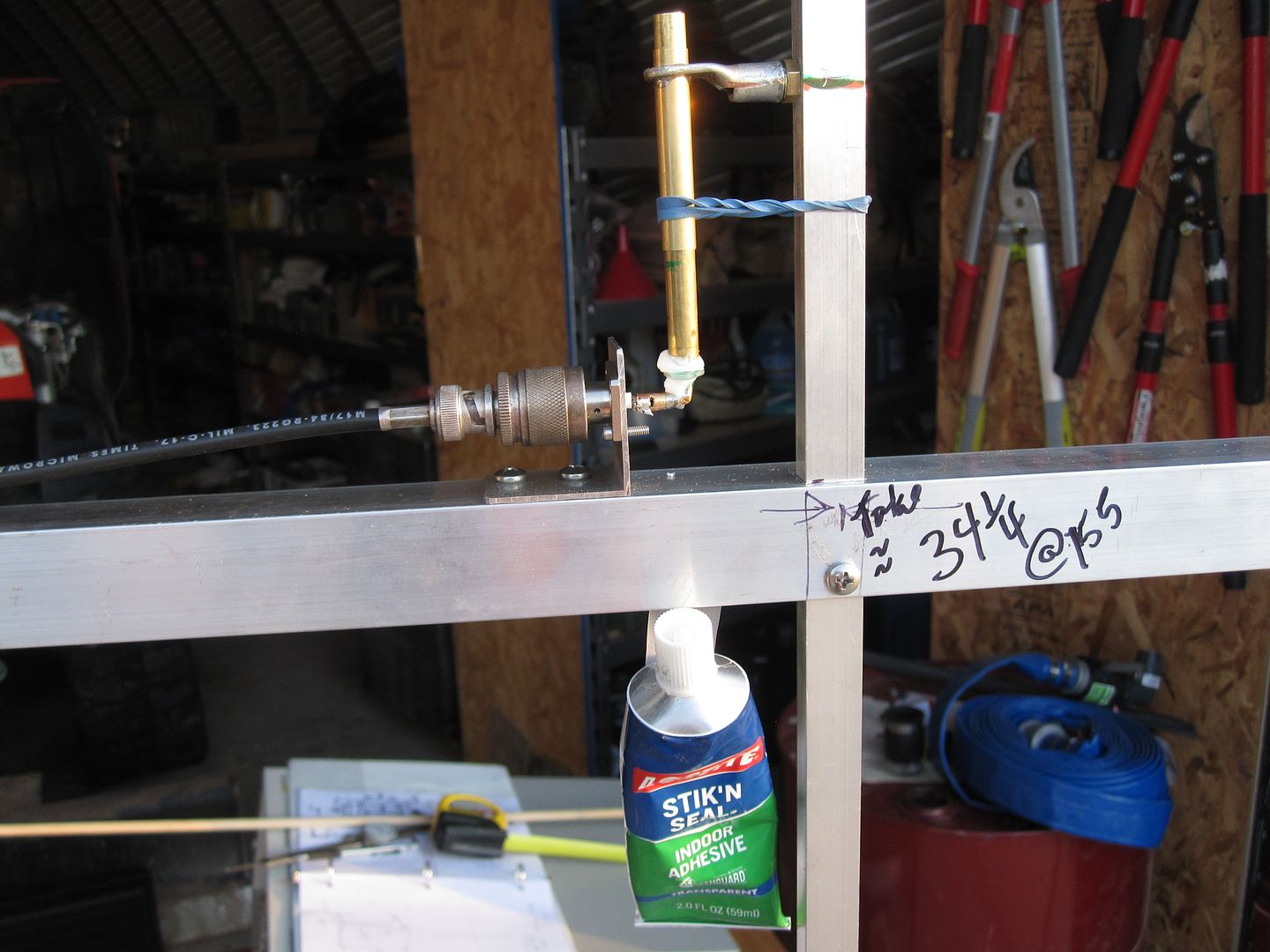
Excellent SWR and the display is 3 MHz per div After the Gamma match components were sealed with a small amount of the Lock-tite stuff, the tuning changed and the elements had to be slightly readjusted. Performance actually improved for some strange reason. 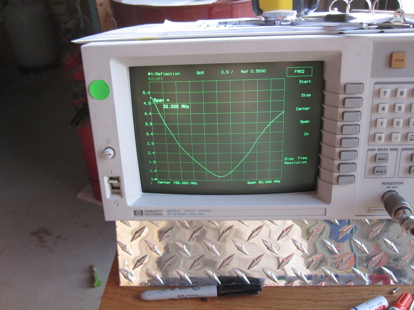
The latest antenna below uses inexpensive channel that 'nests' inside the larger element channel so the elements can be tuned quickly. O-rings secure the tuning stubs to the main elements on all ends. The stubs will be anchored in place with a screw. I've been using old wireless antenna mast mounting hardware and adapting it to the antenna boom. eBay has lots of this used hardware and antennas cheap 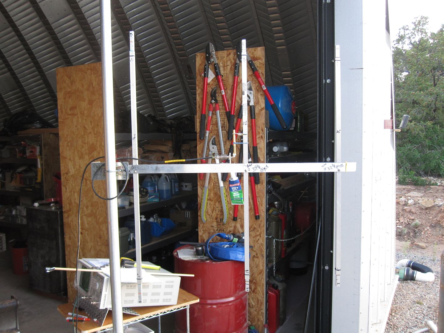
|
|
|
|
[#45]
Built up still another antenna, with a bit more refinement than the one above [and with the same element lengths and spacing]
I'm making up multiple sets of the Gamma match so I don't lose the 'formula' Some pix from yesterday. 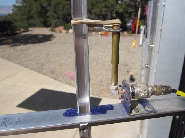
Note screw attaching Gamma Match to element. Could just as well be a small brass strap soldered to the sliding tube and screwed/clamped to the element. Note the outer tube slides on the inner one for easy tuning, and the rubber band holds the 'link' tight to the element. Everything is quickly adjusted for best SWR.. Then there is a 3/16 tube inside the syringe dielectric, notched and bent to a right angle and solder sealed and soldered to the N conx. 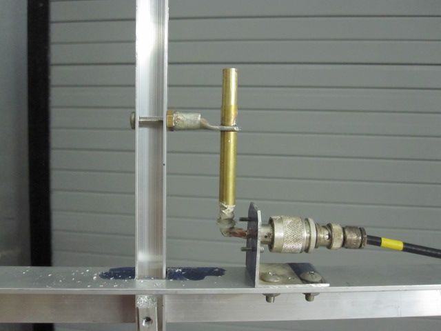
Adjustable element tuning stubs. O-ring to secure initially, then a screw to hold in place. 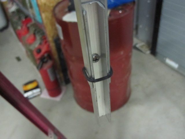
The zig-zag on the left of the network analyzer is quite sensitive to feed line 'dressing. I wrapped about four turns around the antenna mast and it all leveled out went away So, I'm thinking for permanent installation of taking some bare UT141 semi-rigid coax [bought miles of it at a hamfest decades ago] and some waterproof N conx and trying that to run thru the roof of the barn. SWR is good... ~1.1 Minimal sealant is used to not disturb the SWR. Even as the small amount cures, I think I've noticed an SWR change. |
|
|
|
[#46]
Another issue trying to get weak signal reception is all the RFI from the Outback solar chargers, inverters, network switches, etc, and the Axis IP cams on the roof and inside.
The noise was so bad that adding a GasFET preamp actually made things worse. It's working now -that was a learning experience...
Have been doing some extensive testing and have learned that a Sinadder is useful [essential for the $ ?] in quantifying RFI vs. weak signals. Works fantastic. Have set up 2 sig gens on different freqs with a bunch of coax relays to select and to insert attenuation --at a distance, controlled w/ an IP power switch ---for a source of very weak signals. Beacons if you will. These weak signal beacons, just above the noise floor, help to locate and quantify RFI sources. The Axis camera on the barn was jamming the VHF band pretty good, so neatly added aluminum window screen with big hose clamps and reduced noise from it significantly. |
|
|
|
[#47]
Just tested the antenna 2 posts up and it outperformed the antenna before it by a ~2 dB.
Also have some techniques for building up LMR400 cables, the $15 stripper use, and some other LMR400 thoughts/tips if anyone is interested. |
|
|
|
[#48]
There's an interesting article in the January 2016 QST page 45 that explains 'signal capture area' of various antennas...
The article goes into detail regarding dipoles. A Yagi antenna is a dipole with additional elements ['directors'] that induce additional signal into the dipole. Considering, if the Yagi is pointed at the signal source, why would there be a net gain if the signal capture area is the same? Because the directors themselves create additional 'capture area planes' and somehow couple this energy into the dipole as the wave travels perpendicular to the array of elements? |
|
|
|
[#49]
Been meaning to post this info for months...
W-M carries a great DVM made by EXTEK in the automotive dept for abt $18. A fantastic buy. See pix above... I've been a fan of the H-F $4 DVM for almost 20 years because they have manual range selection and are very compact and reasonably accurate and do most anything I need. The new Extek has a beep continuity function and is considerably more accurate, and has the same great functions, is compact, and has manual range selection. Comparing accuracy to a Fluke 179 and an HP 34401A, it is very close in dc voltage. It's the go to now at all locations. This is it to the right of the failed inverter board. 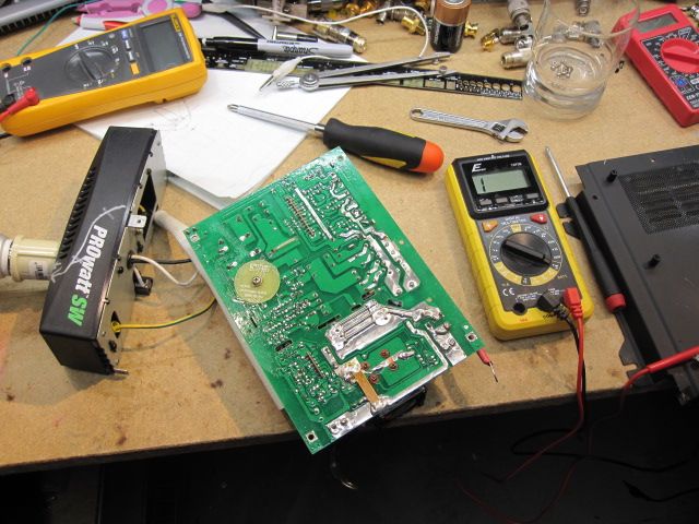
[Caution- It has a lamp [flashlight] in the end and the on/off sw is easily depressed inadvertently. Drill a hole in the plastic lens and break the lamp... I removed the rear cover and clipped the lead to the bulb. |
|
|
|
[#50]
Got in one of these up to 1000 MHz [2.4 ghz] frequency counters.
They're on eBay for about $10... Fantastic buy... 
Hope to hook it up today and report on out of the box accuracy. Meantime, here's a Google link to pix, PDF manual, and at least one video... https://www.google.com/search?q=PLJ-8LED-H&ie=utf-8&oe=utf-8 |
|
|
 Win a FREE Membership!
Sign up for the ARFCOM weekly newsletter and be entered to win a free ARFCOM membership. One new winner* is announced every week!
You will receive an email every Friday morning featuring the latest chatter from the hottest topics, breaking news surrounding legislation, as well as exclusive deals only available to ARFCOM email subscribers.

AR15.COM is the world's largest firearm community and is a gathering place for firearm enthusiasts of all types.
From hunters and military members, to competition shooters and general firearm enthusiasts, we welcome anyone who values and respects the way of the firearm.

Subscribe to our monthly Newsletter to receive firearm news, product discounts from your favorite Industry Partners, and more.
Copyright © 1996-2024 AR15.COM LLC. All Rights Reserved.
Any use of this content without express written consent is prohibited.
AR15.Com reserves the right to overwrite or replace any affiliate, commercial, or monetizable links, posted by users, with our own.