|
Posted: 6/27/2013 8:34:29 PM EDT
I'm trying to setup a stealth HF system as my POA does not allow "antenna masts, towers or poles". I have enough space for a fan dipole to get 20m - 6m. What I am leaning towards is just buying a 20m dipole setup and seeing how my tuner will handle. The only bands I really entertain are 20m and 10m, although I would like to go for 40 but I just don't think I have enough space.
I'm using an FT-897D with the Yaesu tuner. I will also be installing a Diamond x50a for 2m/440 work in the attic. Here's my house: 
Anyone have any experience setting up a similar antenna? My house faces due North, so I'm going to set the antenna to run N/S as to have E/W broadside from dipole. My duct work and air handler are in the attic, just North of the main ridge, think any issues will arise from it? |
|
|
|
[#1]
If you want 20 & 10, you need to do a "fan dipole" setup with an extra dipole for 10m in parallel with the 20m one. Operating 10m into a 20m dipole would put the feedpoint at a very high impedance/high voltage point on the antenna and be very difficult to tune, potentially even arcing within the coax if you used small coax.
Hard to predict how the antenna tuning would be altered by the environment around it, if you have a tuner anyway easy enough to just put up normal dipole element lengths and let the tuner handle the reasonable mismatch. If you have a wide range tuner it should be able to tune for 40m also. If you don't have a metallic ridge vent, would be best to put the antenna up as high as possible for as much of the attic as possible. |
|
|
|
[#2]
Why not a trapped dipole? A trap is a device that "traps" the higher frequency in the shorter part of the wire. The pic below shows a 10, 15 and 20 meter dipole. The traps also "load" the antenna, allowing it to be physically shorter than it would otherwise need to be.
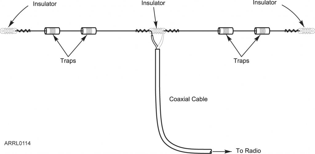
Coaxial traps are simply traps made out of coaxial cable. Wrapped into a coil, they provide significant inductance, thereby allowing you to shorten a dipole; being made of coaxial cable, they also provide some capacitive effect. So you end up with both a coil AND a capacitor for your trap! HERE IS A LINK to a program that will calculate a coaxial trap for you. There is some tradeoff; the coil in the traps causes a small loss of power due to heating. |
|
|
|
[#3]
I'm in a similar situation. Nothing visible from the street as my HOA rules state. So attic antennas it is. They won't get me to the top of the DXCC Honor Roll but has bagged my share of DX.
What has worked for me is the fan concept. Two antennas from one feedpoint seems to be the easiest to work with. Tried 3 and 4 and the interactions between each got to be a big PITA to tune. Tweak one antenna and it would throw off one of the others. There is no rule stating that a dipole has to be straight. Within reason you can bend the legs around obstacles. For example you can run a 40m leg across the north edge, down the west edge, then across the south edge. I highly suggest picking up some electric fence post insulators to keep the antenna wire insulated from the rafters. What has worked for me is say having a 20m/15m fan which with a tuner can get 17m. I've also done a 15m/10m which got me 12m. Currently I have dedicated wire for the WARC bands. How anything in the attic is going to interact with the antenna is anybodys guess. You're just going to have to put up some wire and give it a try. You may as well start considering the purchase of an antenna analyzer. With that you will be able to see where the antenna is resonant and make the appropriate adjustments. In my case I had to offset feed to get the impedance down to a reasonable level. |
|
|
|
[#4]
I have an Alpha Delta DX-20 temporarily strung up in my attic hooked to my FT-950 until I can get something better. There are no problems on 20 at all, obviously. In the lower portion of 10m I can get it to tune with the aid of an external tuner. On 40, even with an external tuner, the SWR is off the meter (meaning over 3 in my case, but I don't have a meter on my tuner, just on my 950) and my power is reduced to around 50w on CW.
|
|
|
|
[#5]
I use two (home brew) attic dipoles for the same reason, and have been reasonably successful with them. My main antenna is a simple, 1/2 wavelength, 20m dipole. I used an antenna analyzer to set it up, and the SWR is no worse than about 1.3 to 1 across the entire band. The tuner in my radio will tune that antenna nicely on 17, 15, 12, and even 30 meters. My second dipole is specifically cut for 10 meters.
Like Hank, I'll probably never get top DXCC honor roll. But I have been able to work a fair amount of DX, and I've already bagged over 100 countries in the 8 months I've been on the air. Total stealth, and I don't have to deal with bad weather knocking down my antennas. |
|
|
|
[#6]
I think everyone is on my line of thinking. I believe the best option for me is to get a 20m/10m fan dipole setup, probably from ebay with a 1:1 balun, center fed.
I can string it up from the ridge down along the Western slope, to give me an inverted V. |
|
|
|
[#7]
As stated above, there's no reason a dipole has to be in a straight line. You could form it into roughly a "Z" shape by running along the peak of the roof and then routing the ends down opposing sides. If you can feed it with ladder line and use a balanced tuner, you should be able to tune it on all bands above 40.
In the attic, use electric fence standoffs to keep the wire away from the rafters. You could even use electric fence wire. Split bolt connectors do away with the need to solder the center point connections. I've worked quite a few hams using attic dipoles. Their biggest problem seems to be receive noise picked up from the house wiring. |
|
|
|
[#8]
Quoted:
Their biggest problem seems to be receive noise picked up from the house wiring. Yep, I have a few birdies caused by house wiring/electronics. They go away when I disconnect the antenna, so they are not in the radio itself. Probably things like the router, and who knows what else. Plus, I was setting off my carbon monoxide detector on a regular basis, whenever I transmitted CW on 15 meters. Solved that one by moving the detector to another location. And my garage door goes up and down when I transmit CW on 20 meters, so I just unplug it whenever I work that band/mode. An indoor antenna can be a challenge, but you can definitely make it work. |
|
|
|
[#9]
Quoted:
At the center feedpoint insulator I solder the wire. That's one place that once set you don't have to mess with it again. The antenna ends is another story. I use split bolts everywhere. Being low in height above ground in relation to where it should be, the impedance is going to be off a bit. So going offset a tad will bring the impedance closer to where it should be. With split bolts its an easy task to adjust the antenna an inch or two.
In the attic, use electric fence standoffs to keep the wire away from the rafters. You could even use electric fence wire. Split bolt connectors do away with the need to solder the center point connections. If you haven't figured it out by now you really need an antenna analyzer. MFJ-259 will serve you well. Rather than buy an antenna, consider making your own. Making a dipole ain't rocket surgery. |
|
|
|
[#10]
Galvanized electric fence wire can be difficult to solder. I've also used the electric fence tape. The width gives a little bit better bandwidth on the higher bands.
The analyzers are worth their weight in gold. Quite a change from the old days when even SWR bridges were a rarity. We just put 'em up, tuned and loaded the ol' 807 for desired plate current, and worked the world. |
|
|
|
[#11]
Quoted: my POA does not allow "antenna masts, towers or poles". A dipole is none of those things. |
|
|
|
[#12]
Quoted:
Quoted:
my POA does not allow "antenna masts, towers or poles". A dipole is none of those things. Visible antenna masts, towers or poles. I'm sure the POA-Nazi's wouldn't discern the difference. |
|
|
|
[#13]
Put a loop around the outside following the lines of the roof. Feed it with ladder line from the soffet via a tuner. This will get you on the lower bands and may hear a little better. 73, Rob |
|
|
|
[#14]
Quoted:
Quoted:
Their biggest problem seems to be receive noise picked up from the house wiring. Yep, I have a few birdies caused by house wiring/electronics. They go away when I disconnect the antenna, so they are not in the radio itself. Probably things like the router, and who knows what else. Plus, I was setting off my carbon monoxide detector on a regular basis, whenever I transmitted CW on 15 meters. Solved that one by moving the detector to another location. And my garage door goes up and down when I transmit CW on 20 meters, so I just unplug it whenever I work that band/mode. An indoor antenna can be a challenge, but you can definitely make it work. The ARRL book on RFI is worth getting. There are some CRAZY RFI causes there! --One guy's garage door would activate when he got on 40 meters. Turns out that the length of the wire running from his motor to the button (the one that opens the door from just inside the garage) was an exact 1/4 length of the 40 meter band! IIRC he just put a few turns of wire in it (close to the opener, it'd work like a choke) and the problem was solved. --Touch control electric lamps are notorious for causing RFI noise. |
|
|
|
[#15]
Hard telling how an antenna will react when close to something. I have a copper pipe slim jim for 2 meters. Its worked great for years outside. I wanted to put it in the attic for use when its storming.
The SWR was fine outside checked it when I put it up inside. It was off the scale. I thought it was a bad piece of coax. Checked it with the OHM meter and it was fine. Pulled it all out and checked it and it was fine. Put it back up same thing. Moved it 10 feet and it was the normal 1 to 1 SWR. Moved it back off the scale. There is nothing up there. Only thing I can think is a piece o flashing under the shingles thats just the right length. Remember wait till its 110 before mounting an antenna in the attic. Same concept of waiting for snow and ice outside. |
|
|
|
[#16]
Quoted:
I have exactly one store bought antenna in the attic. A 6m M2 loop. Got me on the air but I'm thinking of building a moxen for that band.
Rather than buy an antenna, consider making your own. Making a dipole ain't rocket surgery. You will need center insulators/feedpoints, and end insulators. http://www.universal-radio.com/catalog/antsup/5524.html http://www.universal-radio.com/catalog/antsup/5367.html A 500' roll of THHN wire will last you for many antennas. If one doesn't work, take it down, throw the wire at a copper thieves feet and start again. I tried 14ga and found it a bit stretchy. 12ga seems to be fine. Go with stranded wire as it's easier to work with. In official ARF.com orange. http://www.homedepot.com/p/Southwire-500-ft-12-Gauge-Stranded-THHN-Wire-Orange-22970857/202316575#.Uc73NPlJMuc Pick up some wood screw eyelets, split bolts, and electric fence post insulators. For insulators I have a liking for ... http://www.zarebasystems.com/store/electric-fence-insulators/biwkny-z http://www.homedepot.com/p/Blackburn-4-Solid-to-8-Solid-Split-Bolt-Connector-4H-B1-5/100125660#.Uc758PlJMuc Bookmark this ... http://www.kwarc.org/ant-calc.html ----- - Calculate antenna length using the online calculator and add a foot on each end to allow for end termination and to give you some wiggle room for tuning. - Install the terminal at the feedpoint ends and secure with split bolts. - Mount the center insulator somewhere. You'll have to make a wild assed guess as to where depending on what wiring and ducting you have. - Pound in a fence post insulator about every other rafter and thread the antenna wire through it. - At the end go another rafter over and install the wood screw eye. Install the end insulator and tie off with MIL-C-5040 Type 2. (550 paracord) - Once both sides of the antenna are done, hook up the coax and head down to the radio end. On coax length avoid 1/4 wavelengths. Multiples of 1/2 wavelength is the way to go. - Bust out the antenna analyzer and get busy. You'll be making two adjustments. One is to adjust for resonant frequency. The other is to bring the impedance close to where it should be of 50 ohms. - Adjust the resonant frequency by lengthening or shortening both ends the same amount. - Adjust the impedance by offsetting the antenna. Lengthen the hot wire (center terminal of the coax connector) and shorten the ground. A couple inches at an adjustment is all you need. Having a couple inches of excess wire on the end is no big deal and should be left for future retuning if required. If you have 6" of wire hanging off the end that can affect both the resonant freq and impedance. Cut a couple inches at a time and remeasure. Go slowly here as once cut off it's hard to glue it back on. Measure twice cut once certainly applies here. - Once you get down to a SWR of 1.7 or less stop. You're done. |
|
|
|
[#17]
My attic dipole install story and video:
http://www.brickolore.com/2010/12/antenna-install-video.html |
|
|
|
[#18]
Lots of great info.
I'm thinking a trap dipole for 20m and 10m will work for me. Looking at the Unadilla traps/balun. Here's a sketch I did of my roof. The Southern hip ridges are approx. 28 LF each. I also have 4 turtle vents on the rear of the home, so now I'm half way considering running the dipole on the exterior of the roof with christmas light shingle clips, this way I can feed the dipole through a turtle vent. 
|
|
|
|
[#19]
On feedline length, "On coax length avoid half wavelengths. Odd multiples of 1/4 wavelength is the way to go."
Actually, just the opposite. Half wavelength of feedline and multiples are good. 1/4 wavelength and odd multiples are problematic, acting as if shorted. This is calculated taking into account velocity factor of the feedline. |
|
|
|
[#20]
Quoted:
Oh god yeah I screwed that up. Fixed in my post.
On feedline length, "On coax length avoid half wavelengths. Odd multiples of 1/4 wavelength is the way to go." Actually, just the opposite. Half wavelength of feedline and multiples are good. 1/4 wavelength and odd multiples are problematic, acting as if shorted. This is calculated taking into account velocity factor of the feedline. Know what I wanted to say. Brain to keyboard malfunction. |
|
|
 Win a FREE Membership!
Sign up for the ARFCOM weekly newsletter and be entered to win a free ARFCOM membership. One new winner* is announced every week!
You will receive an email every Friday morning featuring the latest chatter from the hottest topics, breaking news surrounding legislation, as well as exclusive deals only available to ARFCOM email subscribers.

AR15.COM is the world's largest firearm community and is a gathering place for firearm enthusiasts of all types.
From hunters and military members, to competition shooters and general firearm enthusiasts, we welcome anyone who values and respects the way of the firearm.

Subscribe to our monthly Newsletter to receive firearm news, product discounts from your favorite Industry Partners, and more.
Copyright © 1996-2024 AR15.COM LLC. All Rights Reserved.
Any use of this content without express written consent is prohibited.
AR15.Com reserves the right to overwrite or replace any affiliate, commercial, or monetizable links, posted by users, with our own.