|
Posted: 9/1/2012 8:15:37 PM EDT
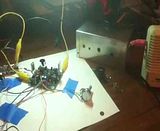
I ordered this last week it shipped Friday and arrived today. Let me first say I am not quite done for two reasons. I want to socket a couple of the parts for easy replacement. My kit was missing 3 capacitors.
I used the NE1RD instructions they are very good but probably not necessary if you have built a kit before and I also was careful to make sure I put the proper parts in for the 30 meter build (the instructions are for a 40). The surface mount part was a bit of a pain but got it done with my crappy radio shack soldering iron with not the best tip in the world. Hope it works. A jewelers loop was EXTREMELY helpful for not only this but identifying small parts. This can easily be built in a night I spent probably 5 hours but I was not in any hurry at all and I really went very very slow and inspected every solder joint as I went along. If I had to build a second one at least the basic board would be done in a couple hours, tops. Probably by the time I get the parts I need to finish this it will be another week or so. Looking forward to getting it on the air if all goes well and I don't let the blue smoke out of something. Crappy cell pic so far. 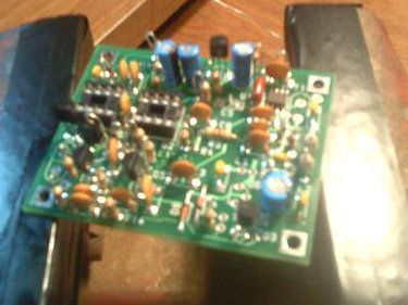
|
|
|
|
[#1]
That is very cool!
I was thinking about ordering one of those kits |
|
|
|
[#2]
 That's awesome, looking forward to hearing you on the air with it! That's awesome, looking forward to hearing you on the air with it!
|
|
|
|
[#3]
This is my 20M rockmite
http://img600.imageshack.us/img600/6093/img1079z.jpg It took me about 4 hours to assemble the board, and another 2 hours to get it all into the altoids tin. too bad I have never learned CW to a level that I could use this thing lol Do you have any ideas for a cabinet yet? |
|
|
|
[#4]
Not sure on the box yet. Could always go Altoid tin I did buy the hookup kit. I might have an issue with fitting it in the tin because I plan to put the crystals in sockets as well as the final transistor, R18 and L1. I hope to buy a 10.115 crystal from NorCal so I can have 2 (I guess 4 if you count the shift built in the rig). I understand you can put a 2N3053 or equivalent in and drop the resistance of R18 down to 6.8 ohms and get just shy of a watt out. The reason I am thinking of L1 as well I have read if you push the power too much you can smoke L1.
Do you know if you can run these off a 9v without modification? The instructions say, "The Rock-mite will run on a 9V battery if R1 and R8 are changed from 1K ohms to 470 ohms. This change increases (receiver) current consumption from ~25 mA to 40 mA when using a 12-14V supply." Just wondered if it would work just not optimally or will it not work at all? |
|
|
|
[#5]
Quoted: Not sure on the box yet. Could always go Altoid tin I did buy the hookup kit. I might have an issue with fitting it in the tin because I plan to put the crystals in sockets as well as the final transistor, R18 and L1. I hope to buy a 10.115 crystal from NorCal so I can have 2 (I guess 4 if you count the shift built in the rig). I understand you can put a 2N3053 or equivalent in and drop the resistance of R18 down to 6.8 ohms and get just shy of a watt out. The reason I am thinking of L1 as well I have read if you push the power too much you can smoke L1. Do you know if you can run these off a 9v without modification? The instructions say, "The Rock-mite will run on a 9V battery if R1 and R8 are changed from 1K ohms to 470 ohms. This change increases (receiver) current consumption from ~25 mA to 40 mA when using a 12-14V supply." Just wondered if it would work just not optimally or will it not work at all? IIRC the Rockmite runs on anything from 9 to 15 volts. The only thing that should be affected is output wattage. |
|
|
|
[#6]
Quoted:
This is my 20M rockmite <a href="http://imageshack.us/photo/my-images/600/img1079z.jpg/" target="_blank">http://img600.imageshack.us/img600/6093/img1079z.jpg</a> It took me about 4 hours to assemble the board, and another 2 hours to get it all into the altoids tin. too bad I have never learned CW to a level that I could use this thing lol Do you have any ideas for a cabinet yet? Looks good. I got the holes drilled in my tin but never got around to mounting it. One of these days. 
|
|
|
|
[#8]
What are you using for an antenna on 30m?
|
|
|
|
[#9]
Lookin good!
Re missing caps: was this a roll your own kit or did you order it from Dave? He's excellent at Customer support, even going so far as to ship me replacements for de-smoked parts. Not to say that you don't need crap from digi-key, everyham needs crap from them, but Dave will replace what's not there, in my experience. My rockmite is on 80m, didn't have any issues with getting it in a tin, but I didn't install a socket for the crystal or final. Do you think you can get a low profile crystal? As far as 9v batteries. One of the first RM's I ever saw was powered by 9v. It was for 20, and on 14.06. At the time he was at about 30 states, trying for WAS. There was no 14.03 option at the time, and his biggest complaint was lack of DX due to digi interference. |
|
|
|
[#10]
Just an observation on my side. Will you be leaving the xtal leads that long? Critical frequency generating parts like that should have leads as short as possible right?
Maybe it is just the way the pic looks. |
|
|
|
[#11]
Quoted:
Just an observation on my side. Will you be leaving the xtal leads that long? Critical frequency generating parts like that should have leads as short as possible right? Maybe it is just the way the pic looks. While I can't speak for the OP's original intentions with this particular set up (aand, I know what I would do, but TIMTOWTDI) I can speak to building practices and general rules. There are several considerations to consider when building a rig: 1. Mechanical issues 2. Frequency stability 3. Design Flexibility. One reason to keep the leads as short as possible is because a component lead is significantly weaker than a circuit trace on a pc board. Stress on a component lead can also weaken or break the connection between the lead and the material inside the component. Milsurp Carbon composition resistors (IE, what you find in Heathkit radios, and others of that era) were prone to breaking internally if you stressed the leads according to my Elmers. While this is still a concern, construction practices can eliminate much of the worry you may have of overstressing the component. Frequency stability is affected by component length because the materials used to make the component ain't perfect. Component leads can contain iron, copper, tin, lead, silver, and other metals based on the use, era in which it was made, and laws governing its making. These materials will introduce stray capacitances/inductances/resistances into the circuit that will affect the frequency of the oscillator and the oscillators ability to oscillate. These effects are more pronounced at higher frequencies. 10MHz is right at about the point where things get tricky. The main problem you will have with keep long component leads is stray inductance. This will deresonate the circuit, and it won't oscillate. I'd say it's no worries in this situation, and the OP is good to go. as far as design flexibility, choosing different crystals is one way, but I would investigate other ways, like building a "Rockless" (see QST, Nov 2009) Just a personal choice. |
|
|
|
[#12]
I actually got the caps from Dave. No problems, I sent him an email and he sent them right out. Customer service was great all the way around.
I do plan to trim the crystal leads just wanted to see if it all worked. I am reasonably patient while I am building so long as I am continually making progress but waiting on the parts (not from Dave) made me a little impatient to just see if the thing worked. Looking like rain tonight so I will probably try to get it all mounted. This is where I got the socket idea. www.barriearc.com/Files/Improving%20the%20RockMite40.pdf |
|
|
|
[#13]
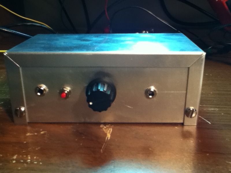
Pretty much done. I didn't have nuts and bolts small enough (amazing with all the hardware I have laying around) to mount the board in the box. I put electrical tape on the bottom of the box to prevent a short and the board is sitting on some double stick foam for now. It's not going anywhere but I will secure it better later.

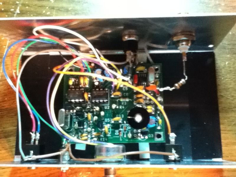
Have to say a pretty cool simple little radio. The side tone and built in keyer are nice features. Frequency shift works as advertised. No contacts yet. My antenna a ZS6BKW really is not a 30 meter antenna with the tuner I have tuned for minimal SWR although the meters aren't moving a whole lot. Anyone want to give it a try tonight who is within a few hundred miles of middle of nowhere Western NY? |
|
|
|
[#14]
It looks great! These little kits are totally cool. I'm going to have to try this, some day.
|
|
|
|
[#15]
Well finally after a zillion calls finally made a contact yesterday afternoon. QSOed with a guy in Marion Indiana a little over 400 miles away. He gave me a 559 but I could tell he was missing a few things here and there.
Also had a bizarre QSO just now on the Pixie 2 I built. I had tried running the pixie off of my power supply instead of the battery which worked fine except I picked up a little noise on the receive. Well I was testing signal strength sending out a few CQ and listening to them on some Web SDR stations anyway I was listening in GA and could here my station faintly when surprisingly a station in WV came back to me. But here is the weird thing I could hear him on the Web SDR receiver online but not over my Pixie. I know the receiver stinks on the Pixie but it generally picks up too much not too little. So I wonder if other stations have come back to me and I just couldn't hear them. Anyway made the QSO work and a 589 from 300mw or whatever this thing is putting out is still not bad over 261 miles. |
|
|
 Win a FREE Membership!
Sign up for the ARFCOM weekly newsletter and be entered to win a free ARFCOM membership. One new winner* is announced every week!
You will receive an email every Friday morning featuring the latest chatter from the hottest topics, breaking news surrounding legislation, as well as exclusive deals only available to ARFCOM email subscribers.

AR15.COM is the world's largest firearm community and is a gathering place for firearm enthusiasts of all types.
From hunters and military members, to competition shooters and general firearm enthusiasts, we welcome anyone who values and respects the way of the firearm.

Subscribe to our monthly Newsletter to receive firearm news, product discounts from your favorite Industry Partners, and more.
Copyright © 1996-2024 AR15.COM LLC. All Rights Reserved.
Any use of this content without express written consent is prohibited.
AR15.Com reserves the right to overwrite or replace any affiliate, commercial, or monetizable links, posted by users, with our own.