|
[#1]
Pretty cool !! What was cost ?
I need a garage badly and trying to decide on stick build or post frame or something like a versatube or similar |
|
|
|
[#2]
The concrete slab w/footings & 12 tons of crusher run was about $2500, the building with all extras (windows, 12 gauge instead of 14 and "certified" with drawings) was about $6K installed with NC tax. County permits ran $200 ($150 for building inspections, $50 for zoning), so total was just south of $9k.
Nick |
|
|
|
[#3]
Been moving items into the building. The plan is adding wheels or dollies for any items I want inside, that way things are man-movable to be shuffled as needed between uses. The finish mower was OK as is. I built the backhoe dolly a while back when the 1025R was stored in the attached garage. The generator is on a carryall whose casters give about 1/4" - 1/2" clearance on concrete.
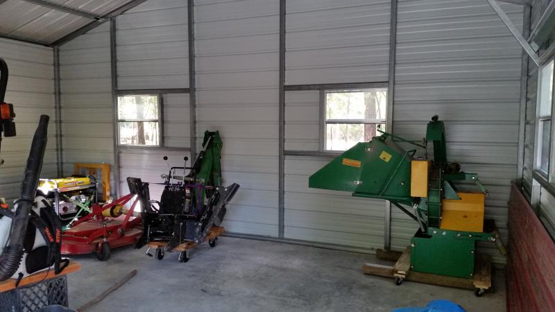
I just added the outriggers with casters to the chipper (the 4x4's on the bottom were added earlier for better PTO shaft alignment with the 3038e & stability when standing alone). The 3 point on the 1025R could barely get it clear of the ground to move it into the building for the modification. The casters only add about 1/2" or so clearance for the 4x4's over concrete, so they should not mire up when it gets set on the ground for use. Nick |
|
|
|
[#4]
i like it.
looking at the picture, i think you should find a way to use for some of the space over about six feet in height. even if it is just higher shelf around the outside edge. |
|
|
|
[#5]
If you don't weld then learning to weld making carts and big shelving for that over 6ft or 7ft stuff would be a decent new project to learn on.
Depending on cost of metal and how much scrap wood you have access to I could see building a loft out of wood though. Do you have plans for a hoist or anything? If built right it could be used for pulling engines or anything and also for putting stuff in the loft. Pay attention to weight ratings and blah blah blah. Nice building, I have not read the thread yet but will read it when I have some free time. I like space, I am terrible about filling every nook and cranny and then it becomes a game of move this to access that. I agree on having stuff on wheels. I buy discounted carts, build my own, have some hand me down stuff, and have a northern tool account I pay for each year and when they really clearance something I tend to load up on it. I have wheels for 4 more dollies, have not bothered to use the scrap wood I have to make em yet. And I don't have much flat floor for rolling stuff around. But what I have, I make full use of. |
|
|
|
[#6]
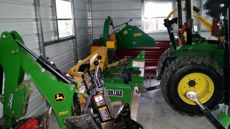
Brought the 3038e back from the acreage (along with landscape blade, rake & box blade - left the rotary cutter there under shelter). Got to see what the building looks like with both tractors in residence.
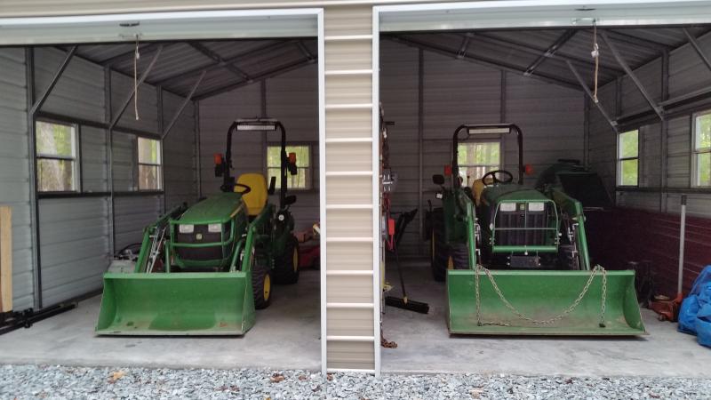
Should still be able to fit in the 60" PTO tiller & maybe the post hole digger (on dollies) - probably leave the dirt movers (box blade, landscape rake & blade) outside if not attached. Nick |
|
|
|
[#7]
Been making more dollies & moving equipment in. So far there, I've added the PTO tiller, post hole auger.
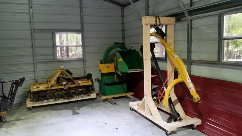
and the box blade to the items moved in. 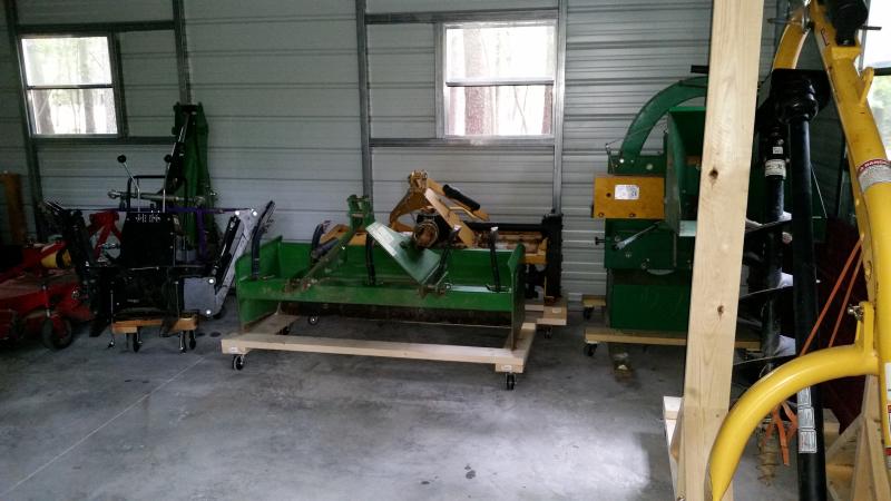
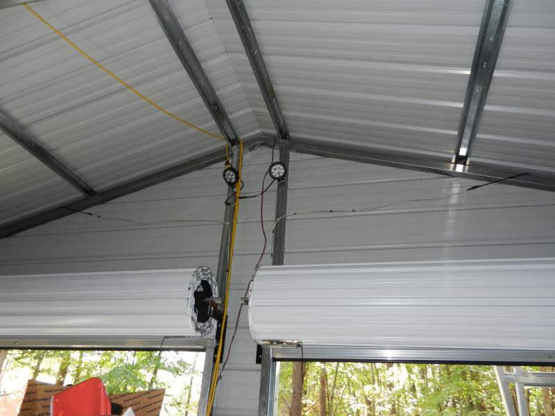
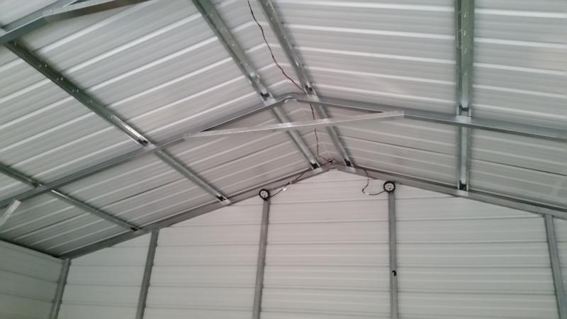
(the 3038e is back a foot and a half or so farther than really needed to close the door) I also added 4 27w 12v LED work lights (flood light - 60 degree spread), putting two up high on the back wall & two on the front wall. Wiring was sourced from an old 50' 14 awg extension cord - figured it would be less likely to get cut on sheet metal. Feed to both sets done via terminating the lines in an anderson powerpole pair. I use a lot of these for radios & accessories, so most of the unassigned SLA's have a pigtail with a set already on... 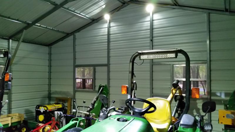
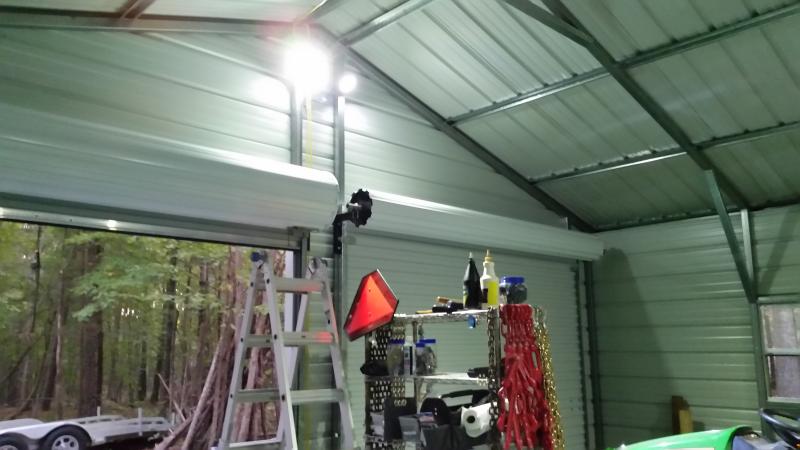
Nick |
|
|
|
[#8]
You have some money tied up in tractors and implements!!
Nice job packing everything in there. |
|
|
|
[#9]
I ordered two more sets (4) of casters & one came in yesterday (the other should show today or tomorrow), so I went ahead with a dolly design for the "landscape" items (rake & blade). I kicked around a couple of different design approaches & settled on an "L" shape for now. I am taking advantage of the rotating feature of both where by putting the lift pin arms more in line with the implement, I get a shallower profile. By using the same shape for both, they can (possibly) be nested.
This is what I put together: 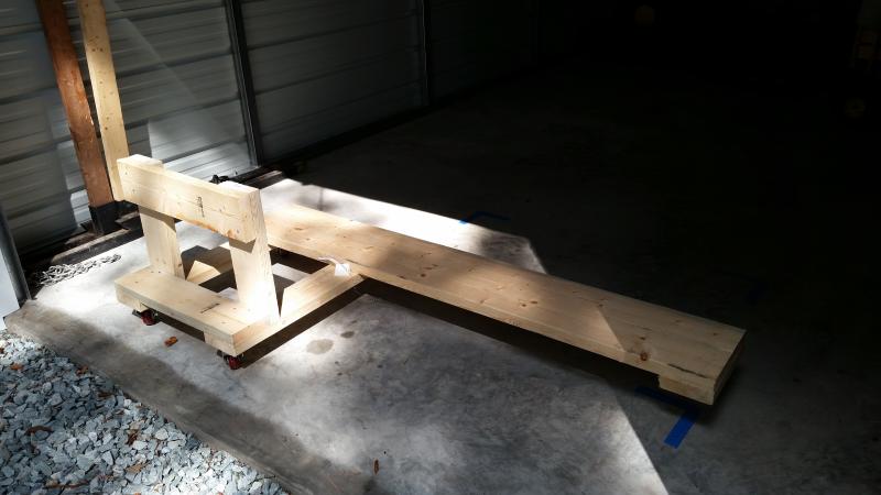
... two wheels on the back, two wheels on the front. 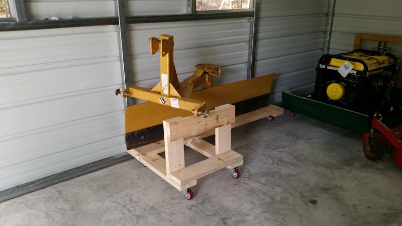
With the blade on it & up against the wall. 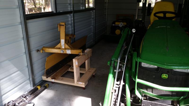
Moved down a bit, another copy could be nested front to front & slightly offset so both only occupy a little more wall space & no more depth. Still plenty of room to get by between dolly & 1025R on this side. I'll update again once the final dolly gets built & installed. Nick |
|
|
|
[#10]
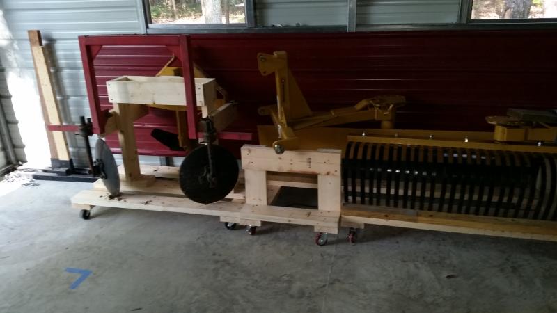
The Fedex truck dropped off the other set, so I built the dolly for the rake. I just finished up moving the rake (on dolly) into its new home. Dimensions are the same, so I just nested it with the blade.
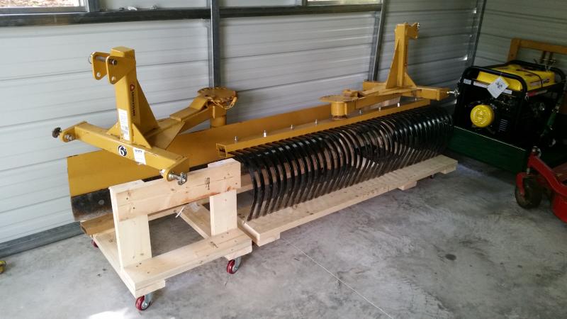
I think I will add a 2x4 back edge for the rake dolly. It had a tendency to "walk" off the back of the dolly while I was moving the lift arms (it was a bit stiff about rotating). A back ledge would take care of that. 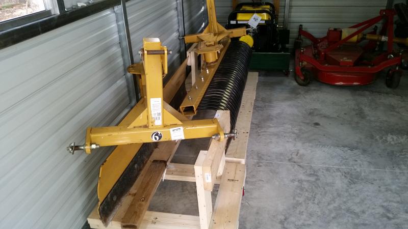
Still room to move around ... 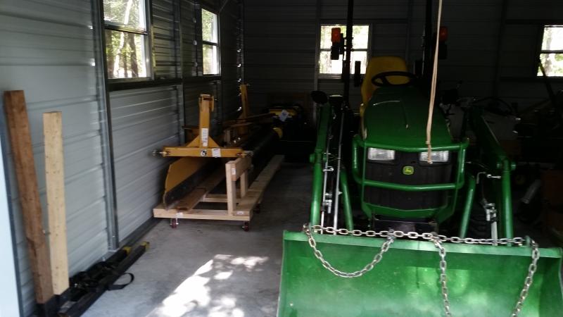
I guess this is pretty much the end of new material regarding the storage building & in-load. Hopefully it works as intended and doesn't become a catch-all for flower pots, rakes & shovels! Nick |
|
|
|
[#11]
Like it, but you need a bigger shed for all of that equipment. Like the roller mounts some of the equipment is on, makes it easy to move around. You also have a lot of trees around the building. They are great for shade but when they start falling for all the various reasons, your building is going to take some hits. You might want to move a few more back.
|
|
|
|
[#12]
Quoted:
Like it, but you need a bigger shed for all of that equipment. Like the roller mounts some of the equipment is on, makes it easy to move around. You also have a lot of trees around the building. They are great for shade but when they start falling for all the various reasons, your building is going to take some hits. You might want to move a few more back. Agreed that trees may become an issue, but it was not an option to clear back to the point where a falling tree could not reach. I may take down a couple more to reduce the likelihood a falling branch could cause damage. The size was dictated by the area I had previously cleared as a graveled parking area extension, which morphed into a pole barn shelter over gravel then a pole barn over concrete, and then finally realized as a four wall metal storage building over concrete ... I did get the last of the implements inside with a dolly for the potato plow (aka middle buster) and hiller. 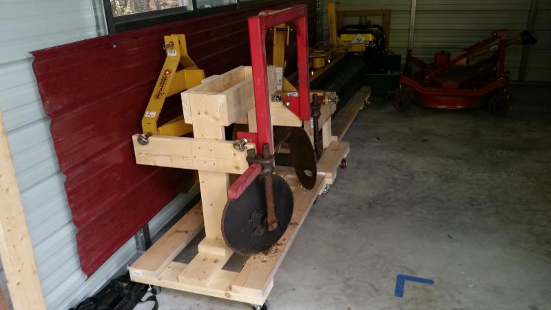
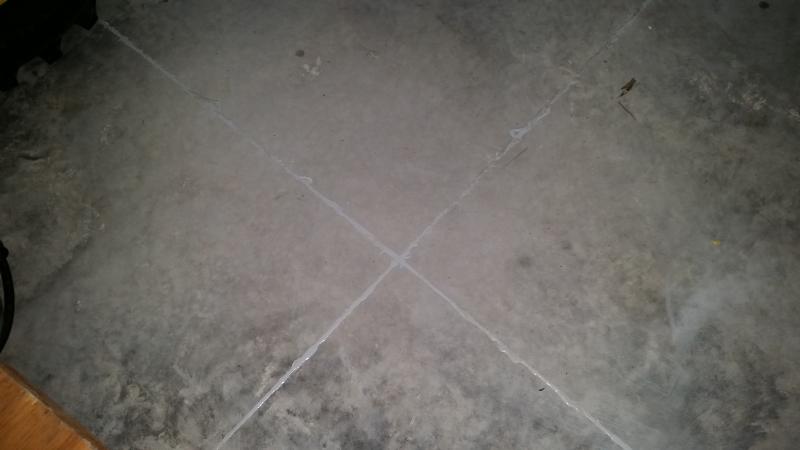
I also added threshold seals and sealed the control joints with some self-leveling filler over a foam backing rod. 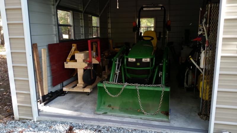
This pretty much finishes up what I was planning to do (except for maybe using some leftover sheet metal from an earlier roofing project to make a buffer on the rest of the wall interiors like the red sheet above). Nick |
|
|
|
[#13]
how large a property are you maintaining with that equipment? What model tractors?
|
|
|
|
[#14]
We have a 3038e and 1025R FILB. We have 4 1/2 acres (mostly wooded) at the house and a 20 acre piece of land about 12 miles down the road that is about 1/2 heavy woods, the rest a mix of fields and some open wooded areas (like park land) formerly part of farmland belonging to the wife's mother.
Got the 3038e back in 2010 to clean up and mantain the acreage and some additional areas nearby belonging to my MIL. Got the 1025R in 2013 to help with woods cleanup and landscape work around the house when my mobility issues were getting worse (pretty much fixed now thanks to a good spinal surgeon). Most attachments were picked up for specific jobs, generally preferring to do work on our own when feasible rather than hire it done. Nick |
|
|
|
[#15]
So that building cost you >$20/square foot? And it looks like you did a lot of the work yourself.
How does that compare to other builders in your local area? |
|
|
|
[#16]
The inspector that came out (also a contractor on the side) said he could not buy the materials for a stick built structure of the same dimensions for what we paid for the installed building.
From what I have seen locally, a stick built of similar size runs $25K-$30K, including foundation (but exterior finish & roof is similar to that of a residence). Materials for a self built pole barn (no sides just roof) would have been ballpark $1800 (w/out tax), locally. Nick. |
|
|
|
[#17]
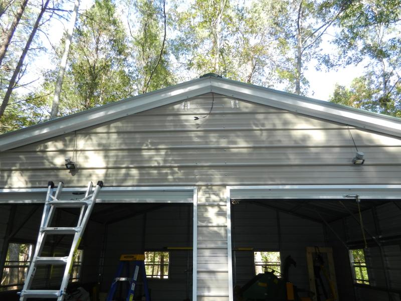
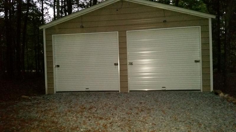
Getting started on a new component for the building. I had already put some 12v lights up on the interior, just using any available 12v battery when light was needed, but just recently decided to make it a bit more "built-in". I've ordered a 100w 12v solar panel and 30amp pwm controller for use with a deep cycle battery that had previously been maintained for CPAP backup (no longer need CPAP). I also ordered a couple of 12v motion sensor 10w outdoor LED floods to mount above the doors outside. I'll need to put together a framework for the panel to be mounted on the building front (oriented due south) just down from the ridge, between the doors.
I'll post some pics once I get some progress. Nick |
|
|
|
[#18]
I'm stealing your ideas for implement dollies and the 12v lighting setup.
Great stuff! |
|
|
|
[#19]
I have gotten started with the solar power add-on for the storage building. I selected a Renogy 100w polycrystalline package consisting of one panel & a 30 amp PWM charge controller. The controller has enough excess capacity for another 3 or 4 100w panels if I want to add them. Here is a pic of the items received today:
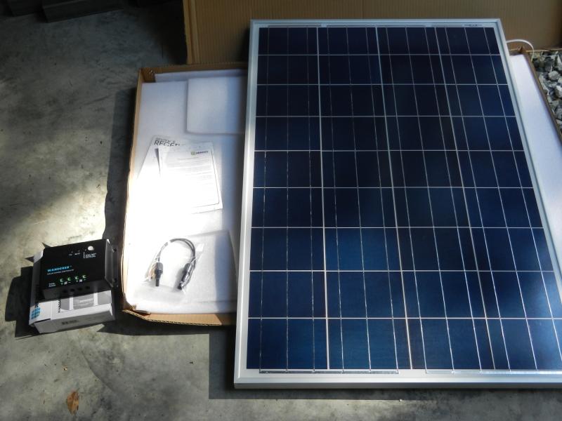
A nice extra touch was the MC4 connector pigtails for splicing if desired (I had already picked up some MC4 connectors & added them to my wiring). The panel arrived with no damage & looks to be in good shape. Here it is producing over 18v (open-circuit, no load) while in the shade and at an almost vertical orientation. In full sun, docs say open-circuit voltage should be 22.4v. I had been waiting for arrival to double check dimensions before putting up any of the outside mounting components. 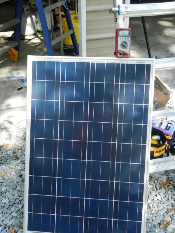
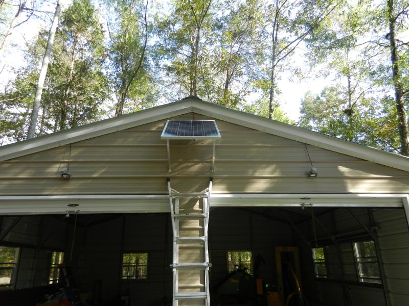
The outside mounting for the panel was fabricated from some 1" aluminum angle stock. I came up with a design that would make it easier to handle dealing with a 17 lb. panel at the top of a ladder by allowing me to hang the panel by a pair of upper connectors with an "L" slot at their ends to be attached to the panel. The upper building brackets consist of two sets of two pieces, each set having a 1/4" horizontal stainless bolt between them from which the "L" slot will then hang. The lower supports include struts that set the desired angle (56 degrees) by connecting with brackets to be added on the lower sides of the panel. 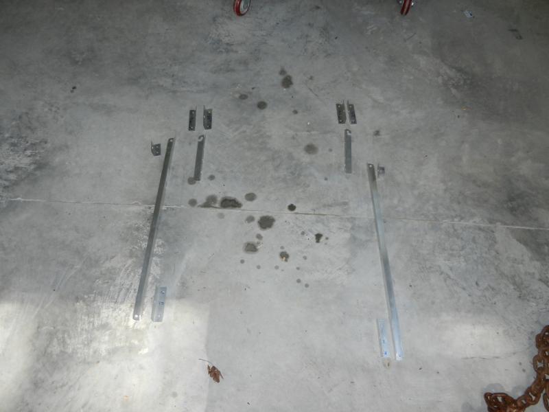
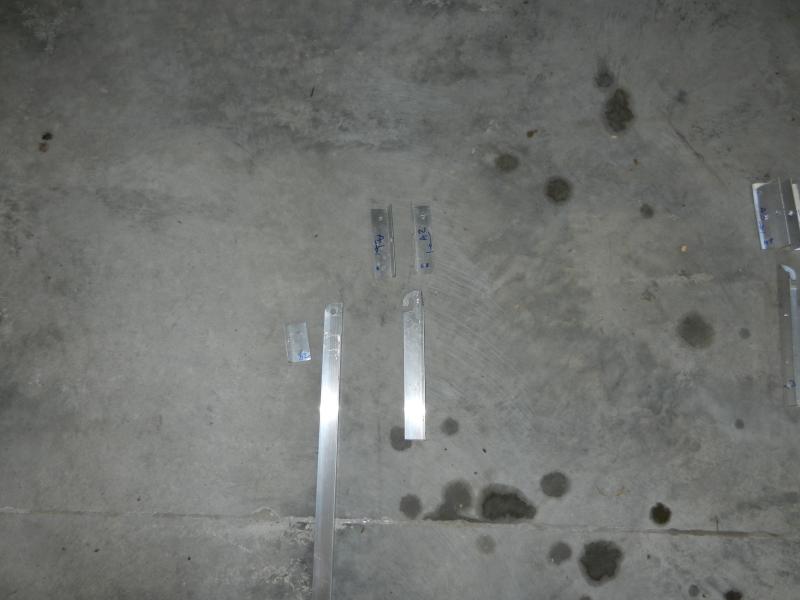
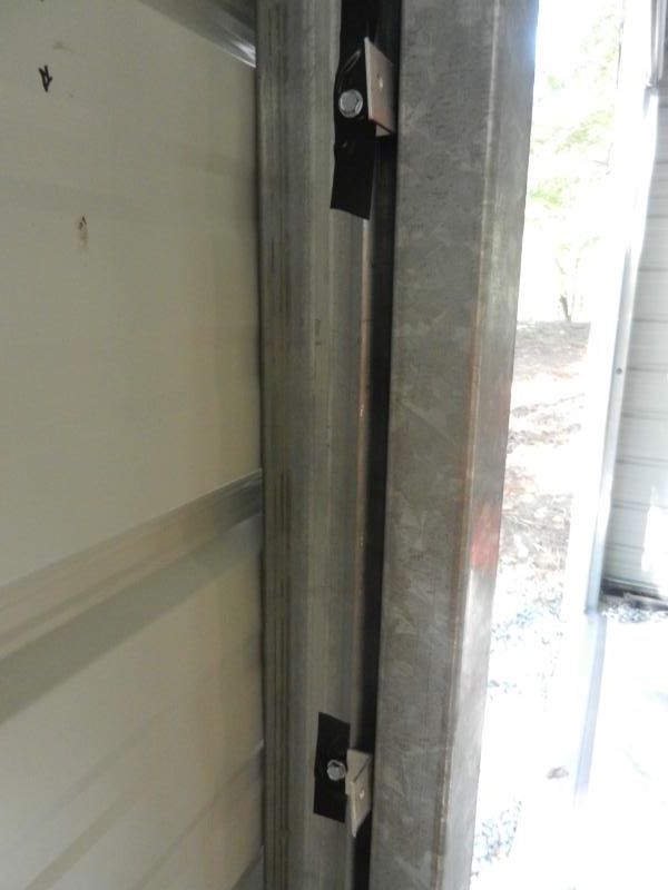
I needed a place to mount the controller, switches, etc. so I picked up a bit of plywood to provide a surface on which to work. To actually secure it to the building, I used some "L" clips made by chopping sections of aluminum angle & drilling a couple of holes. 
I secured them to the vertical tubes that framed the door openings, taping them to hold them in place for screwing in the self tapping screws. 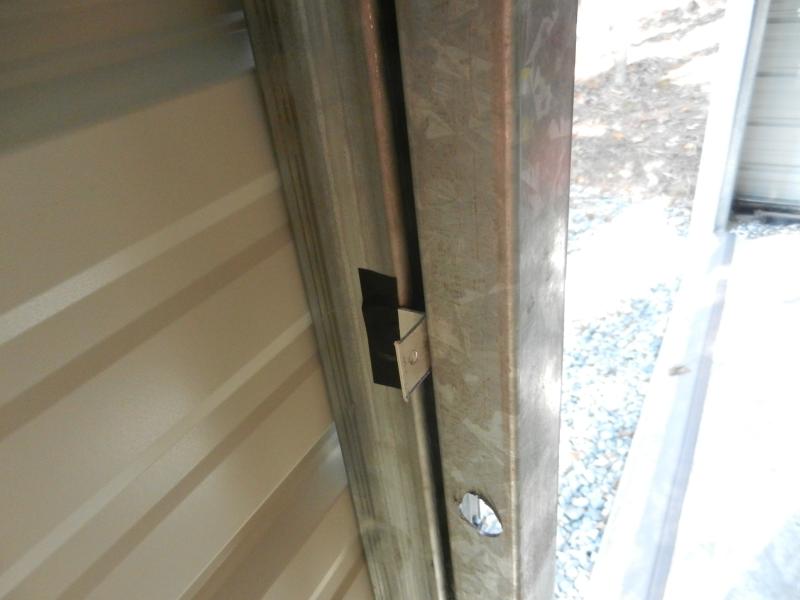
Then the pre-cut plywood section was slid behind the front of the clips & secured with screws. 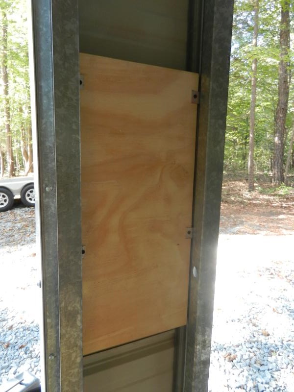
I added some boxes for mounting switches (panel disconnect, interior lights, exterior motion lights). I also used some pieces of IKEA split cable organizer tube for wire trays. 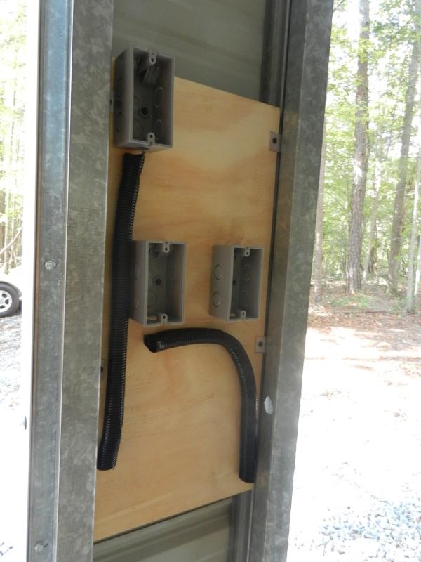
Here the switches are temporarily placed, the pigtail fuses will only be used on the panel feed, lights will come off a fuse block (coming later). The white pair of 12awg is for one of the outside 12v motion sensor floods. They are good for 12v AC or DC, so polarity is not a consideration. 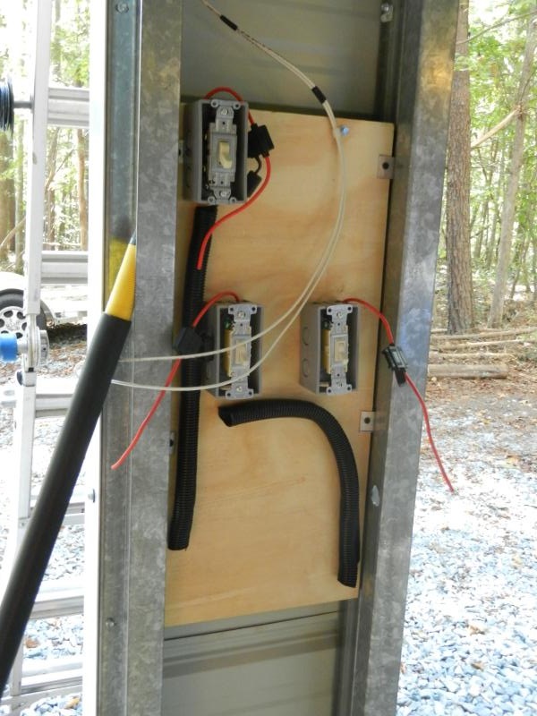
I ran a 10awg pair for the panel feed line & terminated them with MC4 connectors to mate with the panel leads. 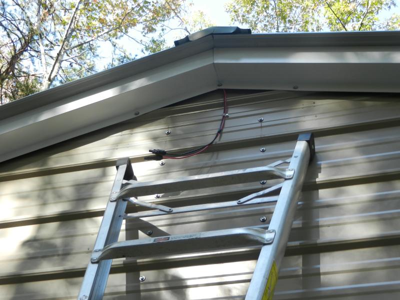
Since I had proper dimensions now, I put the topmost hardware on. There is a 1/4" bolt running between each of the pairs that the panel will hang/pivot on. 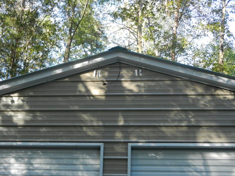
That was the stopping point for today. Tomorrow (hopefully) will see the second motion sensor flood mounted and wired. I also want to get the 14awg extension cord I put up to feed interior lighting replaced with 10awg to reduce voltage drop to the 12v LED worklights. Nick |
|
|
|
[#20]
Quoted:
Brought the 3038e back from the acreage (along with landscape blade, rake & box blade - left the rotary cutter there under shelter). Got to see what the building looks like with both tractors in residence. http://www.skhowell.com/images/1025R-3038e-garage-1.jpg Should still be able to fit in the 60" PTO tiller & maybe the post hole digger (on dollies) - probably leave the dirt movers (box blade, landscape rake & blade) outside if not attached. Nick You have hit my jelly button. I have tractor/shed envy. Very nice setup. |
|
|
|
[#21]
I've been looking at the same Renogy package, although I think I'm gonna go ahead and do two panels since I'm gonna be on the roof anyways.
I think they're going on the roof, that is... |
|
|
|
[#22]
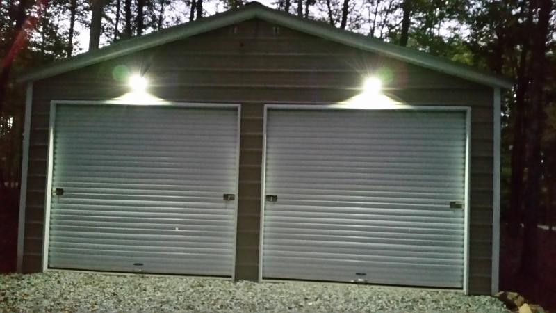
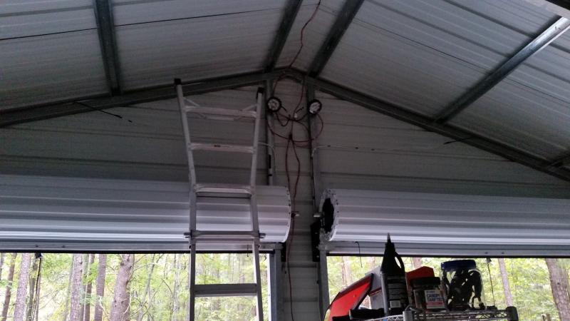
I didn't get much done today, but I did get the second motion sensor up & wired
I also pretty much finished up the wiring panel after the fuse block showed up today. The upper switch is a DPST for disconnecting the PV panel from the controller. It should never be connected if the battery is not connected to the controller. The two lower switches are for the interior lights (on the left) and the exterior motion sensor floods (on the right). 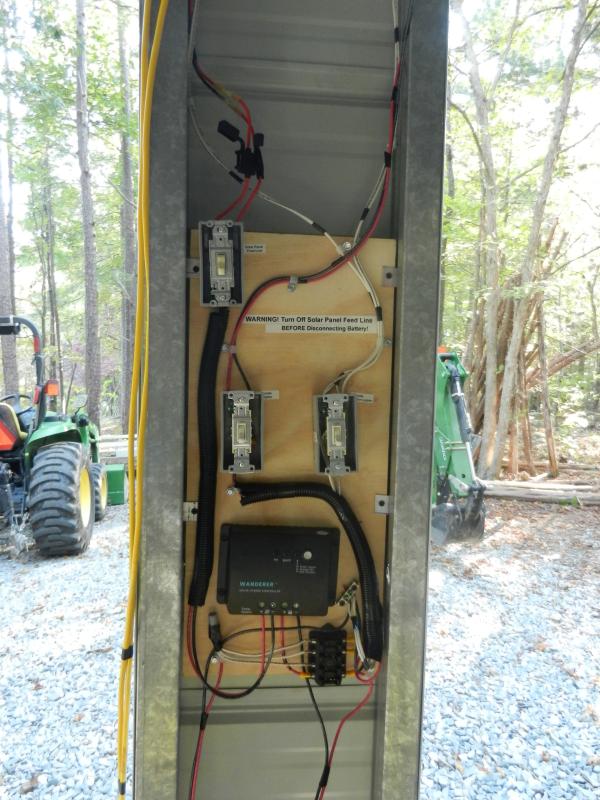
I still need to replace the yellow 14awg interior lights feed with a 10awg run the wires coming off the top of the switch are currently unconnected ... ... I figured I'd wait & put up the PV panel when fresh in the AM. I did put some fuses in & temporarily connect the batter to the fuse block to verify function on the motion sensor lights. I'm waiting on twilight to set the sensors for the floods. Nick |
|
|
|
[#23]
Got the motion floods adjusted, they become active about the same time as the street lights (twilight). The sensors are pointed down toward the area just in front of the doors. Activation duration is currently set pretty short, about 30 seconds of no motion. Their primary purpose is to provide light to get out my keys & unlock the door padlocks.
Nick |
|
|
|
[#24]
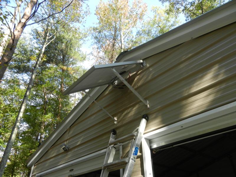
Got the panel up this morning after putting up the bottom support clips on the building. It wasn't too bad getting the panel up the ladder, the Werner folding ladder had steps that extend out a bit from the vertical rails. This let me rest the bottom of the panel on ladder steps as I moved up. The "L" hooks at the top worked as planned and were easily engaged.
Hooking up the MC4 connectors was simple... 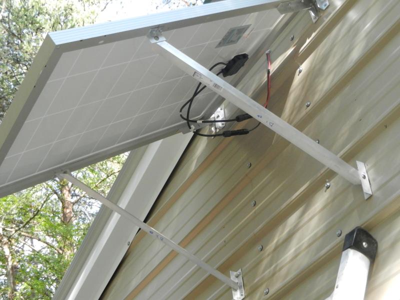
A quick check showed things working. 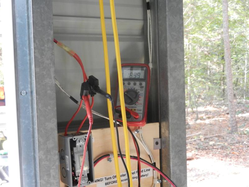
I used a set of post clamps to connect the lines from the controller to the battery instead of the existing Anderson Power Pole connector. You want be sure the panel is disconnected before removing the battery, so I felt this was a better option. The existing Power Pole connectors were used for the fuse block feed lines. This way if the battery is removed (maybe for use with the winch) one of the available smaller batteries can be used for lighting until the deep cycle is replaced. 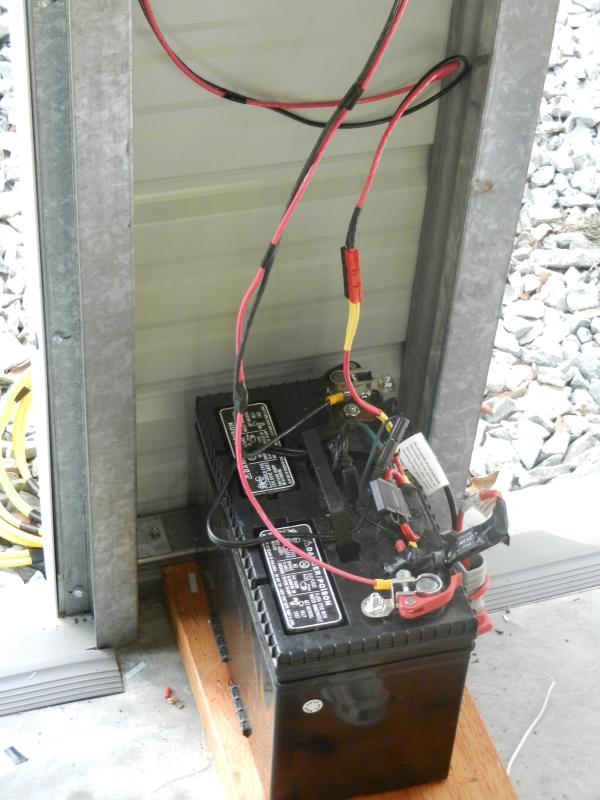
This battery also has a 175 amp fuse going to some large connectors for use with a portable winch with matching connectors. This was set up to allow winching items onto the aluma car hauler (I also have a set of 16' heavy cable & clamps with a matching set of connectors for use with other sources). The controller is set for maintaining a flooded deep cycle battery, that is why the rightmost LED is red. The green LED in the middle indicates standard charging is in process. The left most LED is showing a slow blink green, indicating standard PV operation. 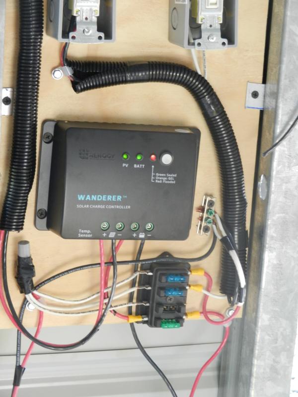
You can see the battery connection to the controller goes through the bottom position on the fuse block, which has a 30 amp fuse installed. There are 15 amp fuses in the slots feeding internal & exterior lights (probably should have used 10's). The in-line fuse holders above the PV on/off switch have 7.5 amp fuses installed (I know the fuse on the negative side is redundant, but did it anyway....). The last task now is replacing the 14 awg extension cord interior light feed lines with a 10 awg pair. Nick |
|
|
|
[#25]
That old yellow cord is gone & a 10awg pair is up in its place. Interior lights are now switch controlled.
That takes care of the last of the work associated with the solar power basics. I do have a couple of DC power monitor displays coming in that will probably get added to the wiring panel. I was curious about the amount of power that is coming in from one PV panel & the amount of power consumed by the interior & exterior lights. It is not a necessary item for the system, mainly just something to play with ... Nick |
|
|
|
[#26]
A side note; I had a couple of little LED DC voltage displays in the junk box, so I figured I'd use them until the monitor displays came in. I hooked up one at the source side of the solar panel disconnect switch, so it would read the panel value even if "off", the other across the fuse box feed & ground connector.
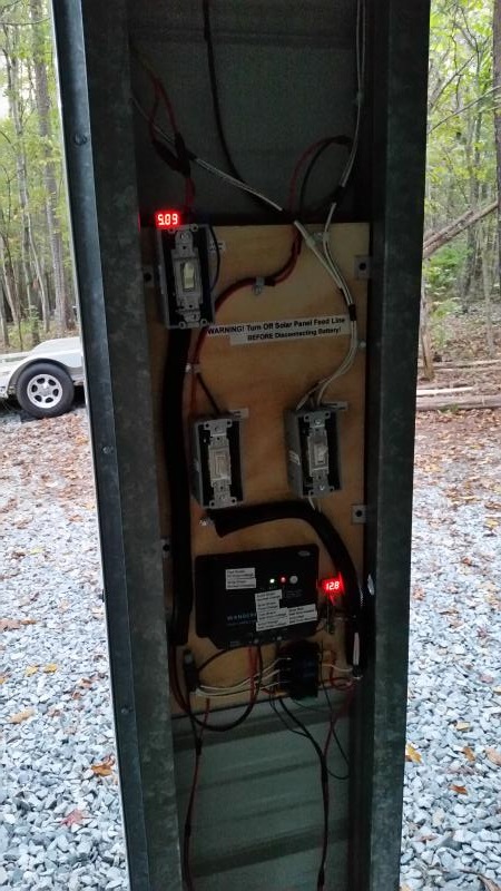
Here they show the values at day's end. It is coming on twilight, sun is dropping below the horizon. The motion floods are currently turned on, but not yet active (not dark enough). The panel readout is 5.09v, the battery readout is 12.8v Nick |
|
|
|
[#27]
looks good.
thanks for the updates. |
|
|
|
[#28]
OP, I can't tell from the photos if you have insulated the building. Do you not anticipate a problem with condensation and dripping?
|
|
|
|
[#29]
No insulation, but have not experienced any condensation issues to date. I keep the 6, screened, windows either fully open (clear weather) or open about 3" (if rain expected), so maybe there is enough circulation to keep things pretty much at homeostasis. There are currently no heat sources that might give off water vapor (except maybe me when in there, but then the roll up doors are open) & the slab was poured on top of a vapor barrier.
Nick |
|
|
|
[#30]
One last (I think...) piece to the solar power thing, I added a couple of monitors, one tracking solar panel output to the controller and one tracking battery power consumption by attached loads (lights, inverter, etc.). This is absolutely unnecessary for a simple application, but I wanted to see the numbers & the cost was modest (about $40 for displays & parts).
Each monitor is using it's own ground connection shunt & they are seriously oversized for this application (shunt is good for 100 amp). This could have been accomplished with just one shunt by tracking controller -> battery vs. panel -> controller. But since one came with each display & I wanted panel side without looking at controller losses, I used two. Displays have optional backlighting, so lit & unlit (top display is solar panel, bottom display is battery use) 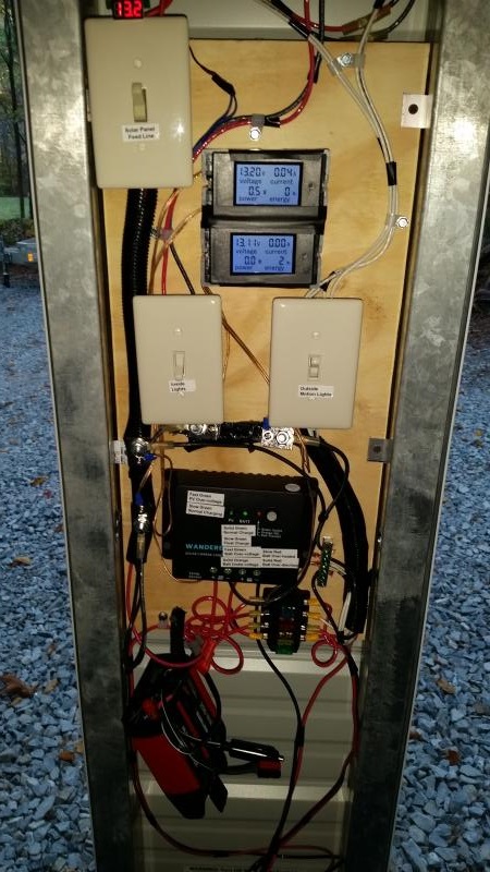 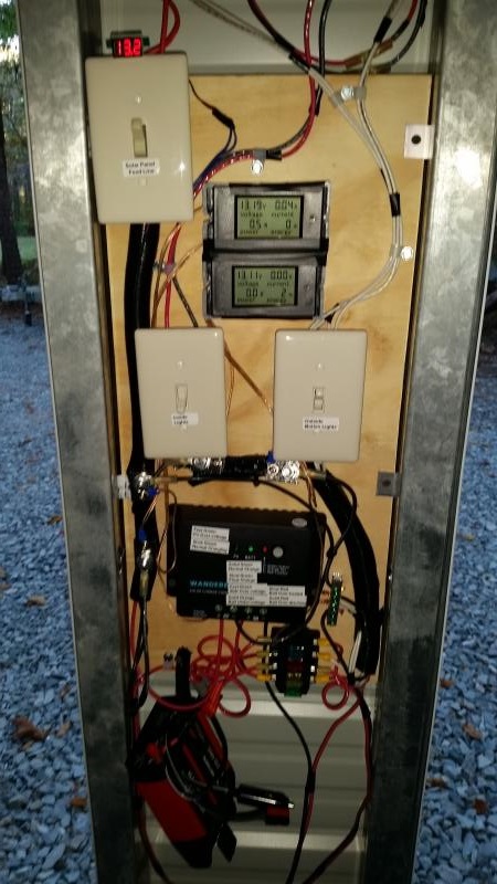
This is right after install & twilight is coming quickly. One thing I have seen so far is that the 27w worklight floods I put up in the interior are actually drawing about 18 watts each, all four on draw about 72 watts total. The displays show volts, amps, watts and accumulated watt-hours. They have the ability to retain watt-hour data, even with power off, until cleared by the operator. If the panel feed is turned off, the top display will turn off, but the LED volt-meter will continue to show solar panel voltage. Nick |
|
|
|
[#31]
Quoted:
One last (I think...) piece to the solar power thing, I added a couple of monitors, one tracking solar panel output to the controller and one tracking battery power consumption by attached loads (lights, inverter, etc.). This is absolutely unnecessary for a simple application, but I wanted to see the numbers & the cost was modest (about $40 for displays & parts). Each monitor is using it's own ground connection shunt & they are seriously oversized for this application (shunt is good for 100 amp). This could have been accomplished with just one shunt by tracking controller -> battery vs. panel -> controller. But since one came with each display & I wanted panel side without looking at controller losses, I used two. Displays have optional backlighting, so lit & unlit (top display is solar panel, bottom display is battery use) http://www.skhowell.com/images/2016-10-24-solar-02.jpg http://www.skhowell.com/images/2016-10-24-solar-01.jpg This is right after install & twilight is coming quickly. One thing I have seen so far is that the 27w worklight floods I put up in the interior are actually drawing about 18 watts each, all four on draw about 72 watts total. The displays show volts, amps, watts and accumulated watt-hours. They have the ability to retain watt-hour data, even with power off, until cleared by the operator. If the panel feed is turned off, the top display will turn off, but the LED volt-meter will continue to show solar panel voltage. Nick I wish one of y'all would do a solar power tutorial...from the basics up...from simple to complex...here in Homestead and Garden. 
|
|
|
|
[#32]
I think the motto for solar projects should be: Location! Location! Location!
The numbers I saw on the meters was not what I had hoped for so I started digging deeper. After checking everything out, the equipment looks fine - but the location kills the efficiency. After checking out the panel by itself "as installed", I dismounted the panel from the wall and took it to full afternoon sun and put my meter on it. It produced, pretty much, as specified in the documentation 22.35 volts open circuit & 5.77 amps dead short (docs say 22.4v @ 5.92A). The installed location pretty much robs it of over 90% of its potential. The best readings, isolated in the installed location, were like 20.5v & .40 amps. Just too much shade. Cost of conductors are too high for relocating the panel (it would take 75 - 100 feet to get beyond shade), so I'll leave it as is for now. It pretty much performs like a smart trickle charger. It does add to the battery charge, just not very quickly. At some later point I may re-purpose the panel & charge controller elsewhere (pond pump or outdoor lighting feature?) & just start swapping out charged for discharged batteries as needed in the building. Nick |
|
|
|
[#33]
I had been playing with some numbers & thinking about the cost/return associated with a better location and using less than optimal conductors. Out of curiosity I built a roughly 65' 10 awg "extension cord" with the MC4 connectors I have on hand to empirically test some of my assumptions about performance with that much of a run. I figured even a 10% loss is no big deal since output at the current location is 95% + lower than optimal.
I removed the panel from the building & took it out by the driveway. Angle wasn't perfect and at about 2:30 PM, so shadows were starting to encroach on the area, but measured 20.9 volts & 4.9 amps directly at the panel. Hooked up the extension cord & measured at the far end, getting 20.7 volts & 4.49 amps. This is a moving target with some shadows moving in and out, but it looks like line loss is going to be no big deal. At the original location on the building, the panel was generally producing less than 0.25 amps (best seen was 0.4), so this is massively better. Going to start roughing out a reasonable mount for the panel that won't offend the wife's sensibilities & will protect the panel from damage from lawn mowing, flying rocks, grandchildren, etc. Nick |
|
|
|
[#34]
OK, this is my initial re-mount of the panel. Might go to a pole mount at a later date, but need to get the utility locator folks to mark phone & power runs before digging. It is a simple cobble-together of 1" EMT & some chain link fence & conduit hardware. The front legs were spread to the limit of the joints & hammered a couple of inches into the ground, as was the rear support, for a bit more stability before mounting the panel. The legs used for the building mount were used to set the angle on this mount, attaching to the emt with self tapping screws.
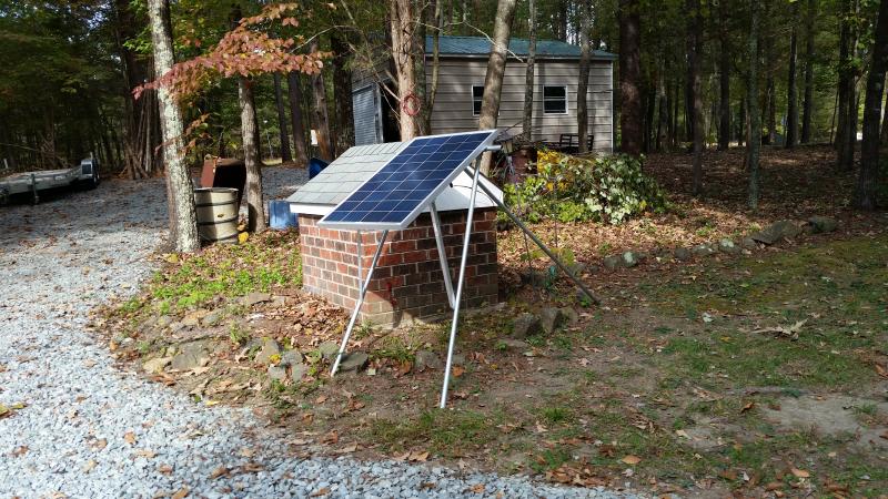
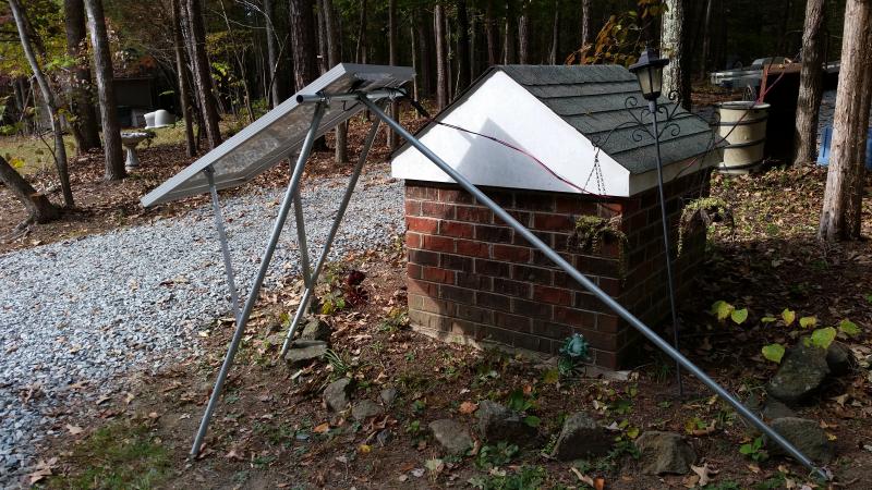
The extension line was run down the eave & then tree supported over to the panel 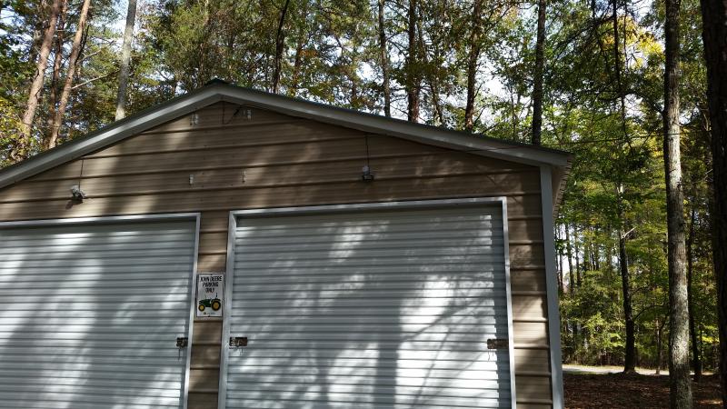
Here it is just coming into pretty much full sun. 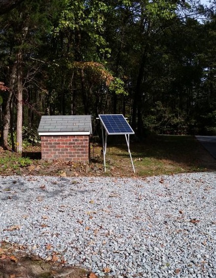
Producing over 50 watts going into the battery (14.56v @ 3.46 amps) for the first time. (Note: a meter proved defective & was pulled pending the arrival of a replacement). 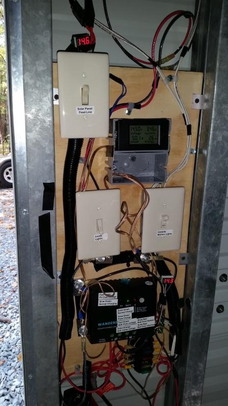
Even with worst case conditions, this location should not produce any less than if the panel were on the building. Nick |
|
|
|
[#35]
Quoted:
OK, this is my initial re-mount of the panel. Might go to a pole mount at a later date, but need to get the utility locator folks to mark phone & power runs before digging. It is a simple cobble-together of 1" EMT & some chain link fence & conduit hardware. The front legs were spread to the limit of the joints & hammered a couple of inches into the ground, as was the rear support, for a bit more stability before mounting the panel. The legs used for the building mount were used to set the angle on this mount, attaching to the emt with self tapping screws. http://www.skhowell.com/images/Solar-20161030-01.jpg http://www.skhowell.com/images/Solar-20161030-04.jpg The extension line was run down the eave & then tree supported over to the panel http://www.skhowell.com/images/Solar-20161030-11.jpg Here it is just coming into pretty much full sun. http://www.skhowell.com/images/Solar-20161030-09.jpg Producing over 50 watts going into the battery (14.56v @ 3.46 amps) for the first time. (Note: a meter proved defective & was pulled pending the arrival of a replacement). http://www.skhowell.com/images/Solar-20161030-12.jpg Even with worst case conditions, this location should not produce any less than if the panel were on the building. Nick That's really interesting. I admit I'm surprised you didn't have more drop over that run. |
|
|
|
[#36]
I think the numbers are held down somewhat by the battery condition (nearing full charge). When I turned on the inside lights (72 watt load), the panel output numbers jumped to 67 watts & 4.7 amps. All the numbers are generated while the panel is attached to the PWM charge controller inputs, which in turn is connected to the battery.
Nick |
|
|
|
[#37]
Well, for the first time since getting started with the solar panel thing, the controller is showing the slow blink on the battery status that indicates it has gone into "Float" charge status, with the battery readout sitting on 13.8v
Nick |
|
|
|
[#38]
Just for fun I ended up with 3 power meters on the wiring panel, one for panel to controller, one for controller to battery & one for battery to fuse block. This is a schematic for the layout:
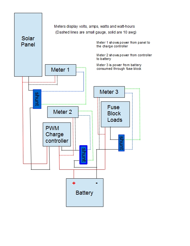
Definately overkill, but I was curious how it looked at those different points. Nick |
|
|
|
[#39]
I haven't posted a shot of the panel in it's final form yet, so here it is with the meter backlighting enabled (usually off). The three meters correspond to the drawing with #1 at the top and #3 at the bottom.
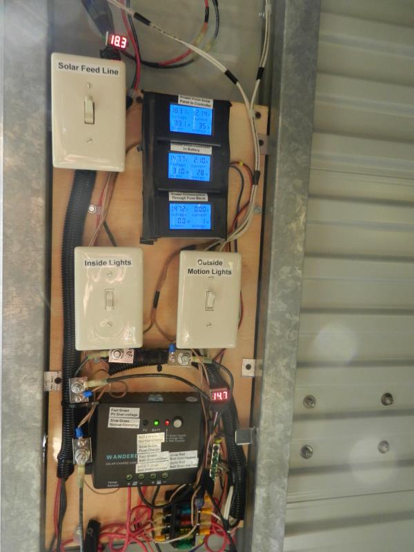
Since it looks like a decent location, I "staked" the three panel mount legs with some 3/8" rebar through holes I drilled near the bottoms. 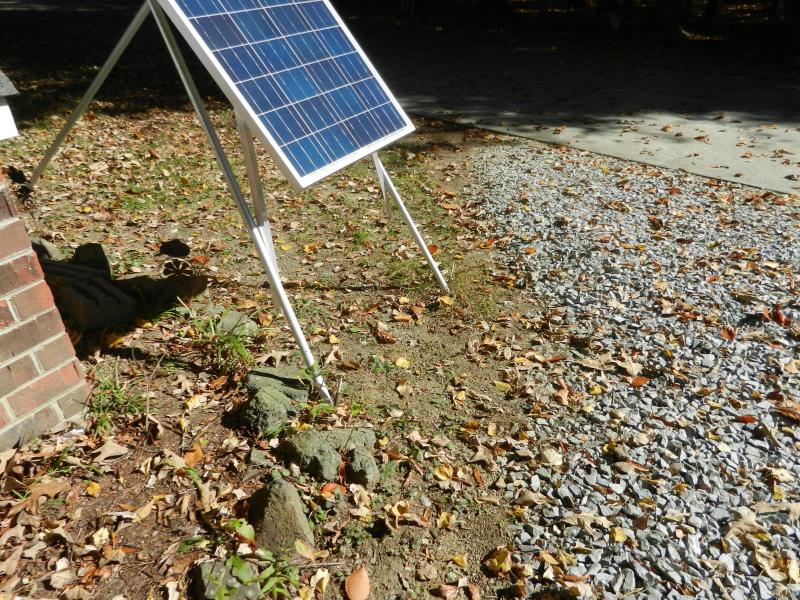
I also set the feed line up with a counter weight (couple of bad 7ah UPS batteries) in case something (branch?) falls across the line. It should act as a shock absorber and help keep anything from getting jerked loose or broken. 
Nick |
|
|
|
[#40]
The squirrels are going to munch on that wire.
|
|
|
|
[#41]
It didn't take long to fill that building up
This is more of a PSA for a good thread. The Fed extended the 30% tax credit for PV and hydronic solar systems. Geothermal is gone .Gov link, just to aggravate them |
|
|
|
[#42]
Very nice work OP. Really liking the the implement dollies.
Your electrical/solar skills are beyond my abilities, but I think I will purchase that solar system. Thanks for this link to this thread. |
|
|
|
[#43]
Small update. Just after Thanksgiving I put up a Christmas tree form (pipe + paracord radials) out by the building, trimmed with LED lights and an LED trimmed ball form. I am running a 200 watt inverter off the battery (smallest inverter I had...), with a mechanical timer in line to control the lights so they come on around 5:15PM & go off around midnight. With the lights off, the inverter & timer combo are drawing about 3.5 watts. With the lights on, the load is about 17 watts. This is an addition to the normal use associated with the outside motion floods.
So far, the solar charging system is staying ahead of the nightly draw down with sunny days making up for the deficit that occurs during the overcast days. Here is the tree with about 240 LED's, not shown is the tree hung ball with about 170 LED's that was added after this pic (but are included in the 17 watt load). 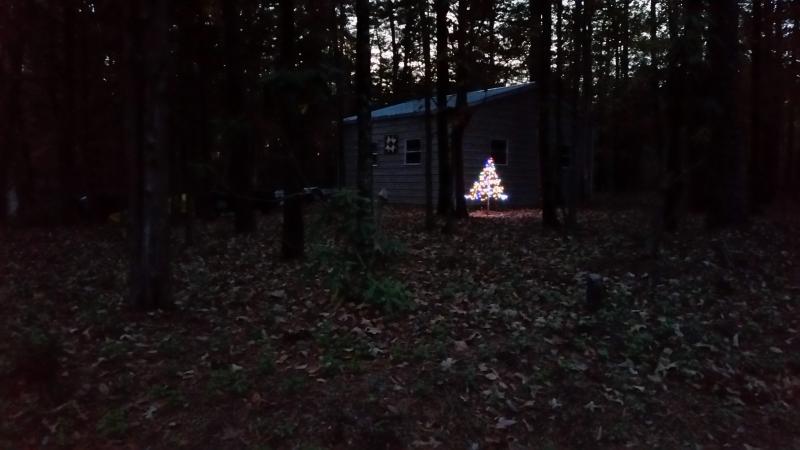
Nick |
|
|
|
[#44]
Thanks for all the great info as we may be building a metal building in the next year or so for similar storage.
|
|
|
 Win a FREE Membership!
Sign up for the ARFCOM weekly newsletter and be entered to win a free ARFCOM membership. One new winner* is announced every week!
You will receive an email every Friday morning featuring the latest chatter from the hottest topics, breaking news surrounding legislation, as well as exclusive deals only available to ARFCOM email subscribers.

AR15.COM is the world's largest firearm community and is a gathering place for firearm enthusiasts of all types.
From hunters and military members, to competition shooters and general firearm enthusiasts, we welcome anyone who values and respects the way of the firearm.

Subscribe to our monthly Newsletter to receive firearm news, product discounts from your favorite Industry Partners, and more.
Copyright © 1996-2024 AR15.COM LLC. All Rights Reserved.
Any use of this content without express written consent is prohibited.
AR15.Com reserves the right to overwrite or replace any affiliate, commercial, or monetizable links, posted by users, with our own.