|
Posted: 10/22/2014 1:25:58 PM EDT
4 HP diesel engine/ Leece Neville 12 volt alter--charging battery bank Part 2 W/ data...
Here's a thread that's been archived re a Kubota 4 HP engine powering a Leece Neville alternator. Kubota genny PART 1 Recently, an instrument panel has been added: 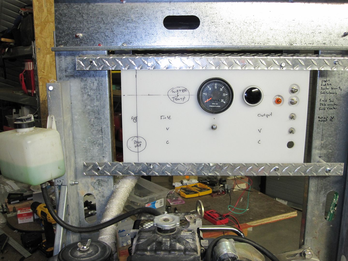
Here's the business part... 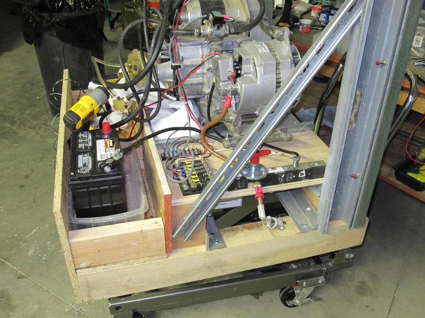
A Scepter fuel can sits in the 'shelf' next to the battery and here's the way the fuel system is plumbed to the fuel can. I changed the way the genny was mounted to the H-F hydraulic table. The genny now has provision to sit on 4 x 4 skids, be raised on the table or be moved with a pallet jack. 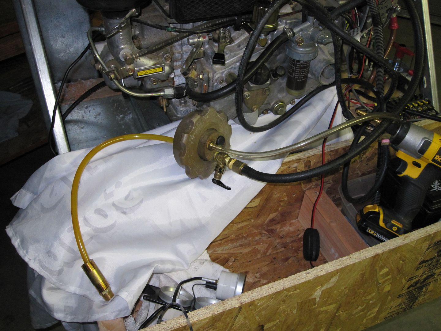
The clear hose is the fuel return from the pump... |
|
|
|
[#1]
Nice
|
|
|
|
[#2]
Overall pix of the genny system as of this ALMOST moment... Another gauge has been added...
With the BPA free instrument panel from W-M for the nervous Nellies... 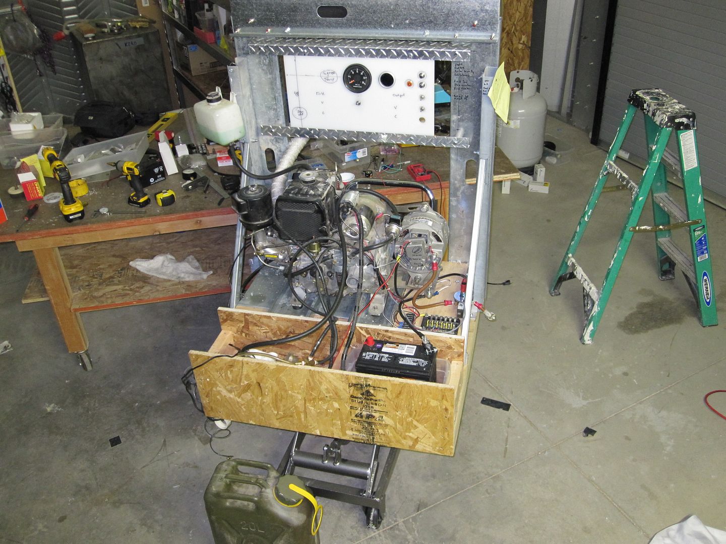
Note the Freightliner tach... It works! I run at abt 2000 RPM. Can't see it in the pix- I took a tach from a truck engine and made a mounting arrangement to couple it magnetically to the ring gear on the Kubota. The calibration fell in nicely. I used a grease gun flexible 1/8" NPT hose to connect the oil gauge port on the Kubota to the sender about 12 inches away. It was too cluttered around the oil fill port and filter to mount the sender on the engine. I wonder if the rubber in the grease gun hose will hold up OK? |
|
|
|
[#3]
Very cool, But what is this going to be used for?
|
|
|
|
[#4]
|
|
|
|
[#5]
AAh! very cool indeed!
|
|
|
|
[#6]
Very clever set up. I have had a similar alternator for some time, been pondering how to best power it up. Thanks for the tip.
I think the rubber will be okay with the oil, petro product switched to petro product...but I get your drift. Might be worth the effort to build a copper line with ferrels etc. for a permanent set up. I am sure you know but avoid that nylon tubing...always fails when you don't want it to. That has been my general experience with the stuff anyway. |
|
|
|
[#7]
I suck at electric but did you get it to run at lower amps with a rheostat? How is that setup?
Im a look/hear kinda persoin not a read/pictures. |
|
|
|
[#8]
Quoted:
I suck at electric but did you get it to run at lower amps with a rheostat? How is that setup? Im a look/hear kinda persoin not a read/pictures. There's a link at the top in the orig post to the Part 1 that got archived. It has a lot of data re output current with a var resistance in the field. Also fuel consumption at certain loads. The next step in the next couple days is to instrument both the solar/battery dist system and the genny with 3 of these... [Just grabbed a pix off Google, these are AC, the ones I'll use are similar for DC current and voltage.] 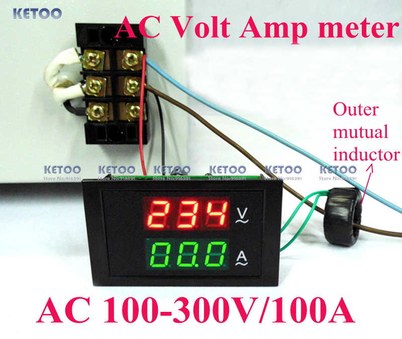
Then I'll be doing some more testing of regulating output current. In the pix of the instrument panel, the rheostat goes on the left side and the LED readouts in the middle. I'm cutting a grey plastic small [NEMA] cover to mount the LED readouts. Maybe I'll put the genny readout on the power distribution panel inside so I can see it with the IP cameras, because the genny will mostly run outdoors, altho I'll make provision to run indoors with remote engine start/run controls -later... Maybe. I have everything to do it already. Have to think abt this... |
|
|
|
[#9]
Where would be a good place to find an engine like that ?
|
|
|
|
[#10]
Quoted:
Where would be a good place to find an engine like that ? Reefers, but hard to find... |
|
|
|
[#11]
Expy-
Looks great. Nice job, However, points deducted because it is not painted camouflage. 
|
|
|
|
[#12]
Quoted:
Expy- Looks great. Nice job, However, points deducted because it is not painted camouflage. Thank you! I appreciate that you appreciate the hard work. Did a lot more work on the solar power system and genny today. Have a lot of pix in my email to upload for both systems. Most of the work involved interfacing the genny power to the solar power panel, revising the disconnects for the genny on both sides, installing some shunts and meter, etc. Thought about the interconnect between the genny charger and the power panel and rewired the genny in two fused branches to the inputs of the big 150 amp circuit breakers -on the battery side. That's so if the CB's both trip, all none of the electronics see anything nasty from the genny/alternator. A lot of stuff. Eating now, will go back to it in a little bit. |
|
|
|
[#13]
Also found that one of the big breakers had too high a voltage drop across the contacts. Been watching it a few days and could feel a bit of temp rise thru the Bakelite at the location of the contacts, during high charge periods from the panels.
So today I drilled a small hole thru the plastic where the heat was and sprayed some contact cleaner inside. Seems to have fixed the issue. At say 30 amps, the drop is abt 80 mv. |
|
|
|
[#14]
Nice OP
|
|
|
|
[#15]
Here's a pix of where the breaker got drilled and injected during it's brain surgery...
Symptoms were high contact resistance/voltage drop at higher currents. A long slender drill used for cranial biopsies is pointing to the hole drilled in the patient. 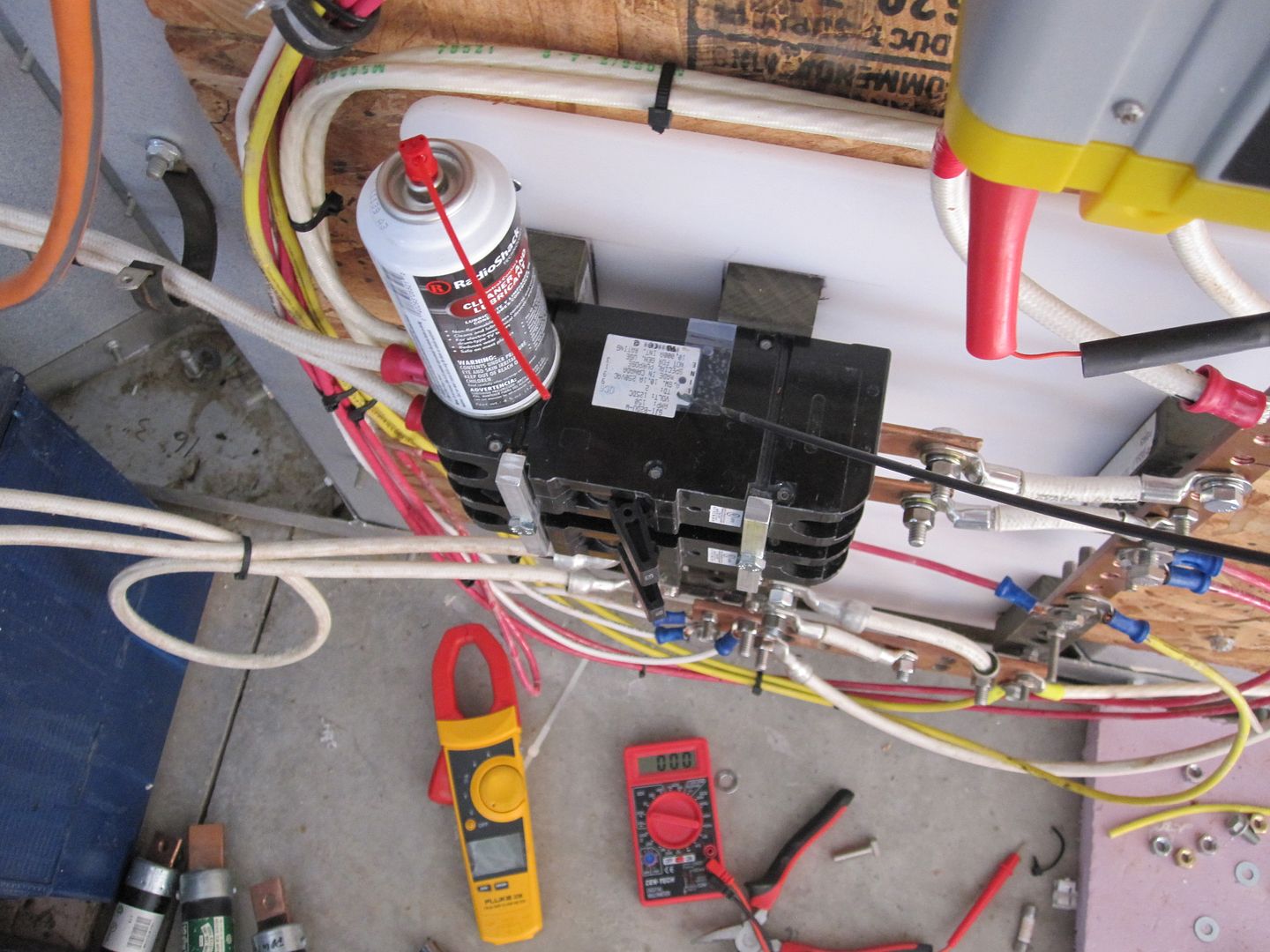
|
|
|
|
[#16]
Here's the prep and results of the high current cable that will supply the battery bank from the Kubota generator.
I put the #4 cable in a protective nylon sleeve. One thing I didn't do at this point is provide a 3rd 'sense' wire between the battery bank and the alternator. It can be added real fast. Laying out the cable and sleeve... 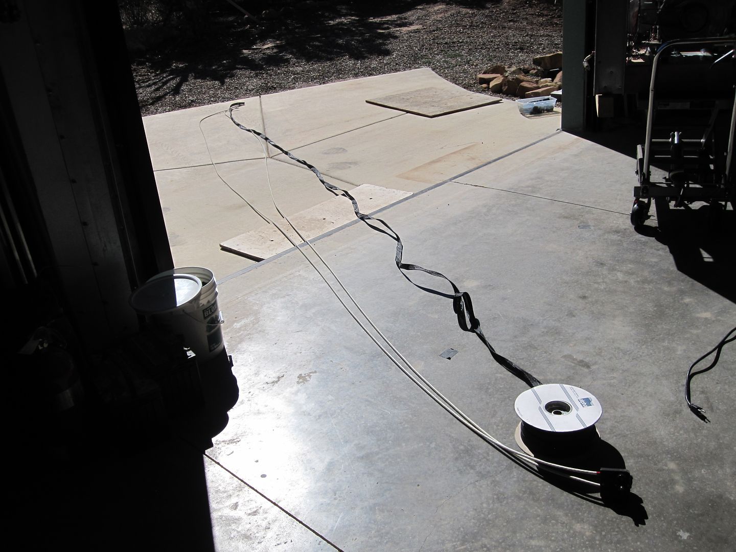
Everything assembled and looking great... 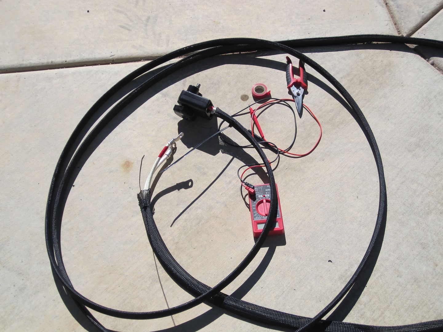
Here's the aircraft battery connector mounted in the wall and the mating cable assembly connector... 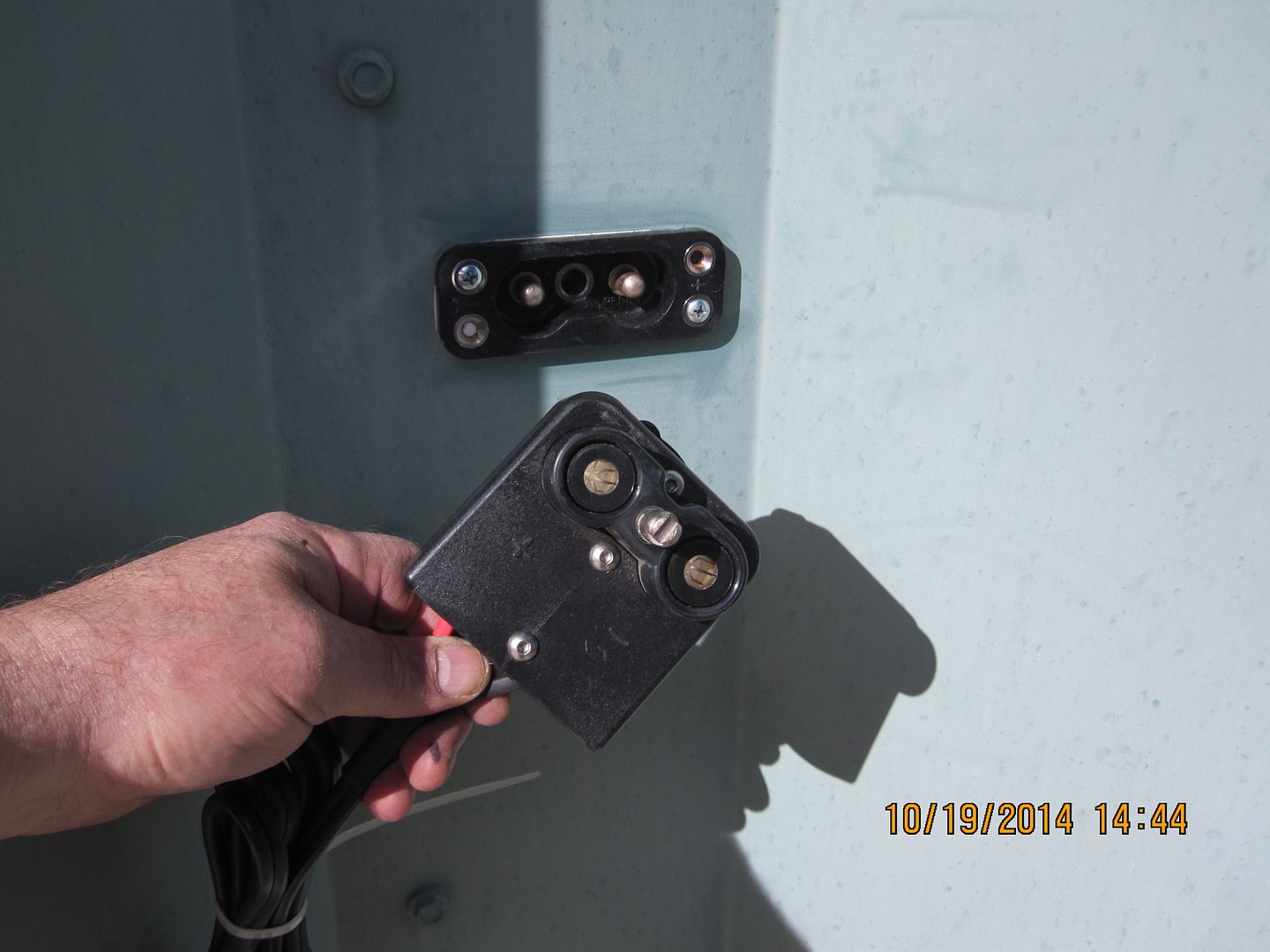
|
|
|
|
[#17]
Yep, gonna have to add a sense wire.
Just ran it and have abt a volt and 1/2 drop from the alternator to the distribution panel. At 55 amps. Had to turn all the Outbacks' off to get the system to draw more than abt 25 amps from the genny. The engine runs smooth and is fine at 1900 RPM. So, will add a 3rd wire now and see what happens. |
|
|
|
[#18]
Just tested, will have to remote sense both the neg and pos terminals.
It appears it's easy with these alternators. Gotta love Leece Neville! |
|
|
|
[#19]
Quoted:
Here's a pix of where the breaker got drilled and injected during it's brain surgery... Symptoms were high contact resistance/voltage drop at higher currents. A long slender drill used for cranial biopsies is pointing to the hole drilled in the patient. http://i994.photobucket.com/albums/af66/expy37/KUBOTAgenrev3186_zps887de802.jpg do yourself a favor and REPLACE that circuit breaker. Your supposed fix is temporary at best and an extreme hazard at worst. Shoot me a pm if you would like an in depth explanation of why this is not a proper fix. |
|
|
|
[#20]
Quoted:
do yourself a favor and REPLACE that circuit breaker. Your supposed fix is temporary at best and an extreme hazard at worst. Shoot me a pm if you would like an in depth explanation of why this is not a proper fix. Quoted:
Quoted:
Here's a pix of where the breaker got drilled and injected during it's brain surgery... Symptoms were high contact resistance/voltage drop at higher currents. A long slender drill used for cranial biopsies is pointing to the hole drilled in the patient. http://i994.photobucket.com/albums/af66/expy37/KUBOTAgenrev3186_zps887de802.jpg do yourself a favor and REPLACE that circuit breaker. Your supposed fix is temporary at best and an extreme hazard at worst. Shoot me a pm if you would like an in depth explanation of why this is not a proper fix. Please send me an internal message, I'm curious. I expect it to live a long and happy life, if it doesn't no biggy. And I will let you know if it doesn't. |
|
|
|
[#21]
Today, I'll use some random unusual NEMA AC type connectors to mount in the barn wall above the 12 volt conx and on the end of the orange extension cord that is salvaged for some nice well protected 12 gauge wire to run the sense signal between the power panels and the alternator.
Also, a connector on the genny, so it only takes a few seconds to hook up. I'll mount a DPDT switch on one of the genny panels maybe the triangular one to switch between local and remote alternator sense. This triangular corner of the genny has the first iteration of power output for testing. So it had to be upgraded to something more technically pleasing and so I cut a piece of UHDP into a sort of triangle and mounted it that space. A battery disconnect switch, heavy terminals for connecting the made-up cable, shunt, fuse, and some other stuff goes into this panel. I can't find a pix of the new panel, will have to upload one later.
Incidentally, the big box stores have 15 x 20 inch cutting boards of the UHDP that make a great source of inexpensive material for all sorts of survival and ham radio related projects for abt $9. They are easily cut with hand tools, they're ~ 1/2" thick and sometimes components won't fit and the plastic is easily thinned with Forstner or spade bits in a drill. Here's the panel being cut... Like butter, but they are surprisingly strong. 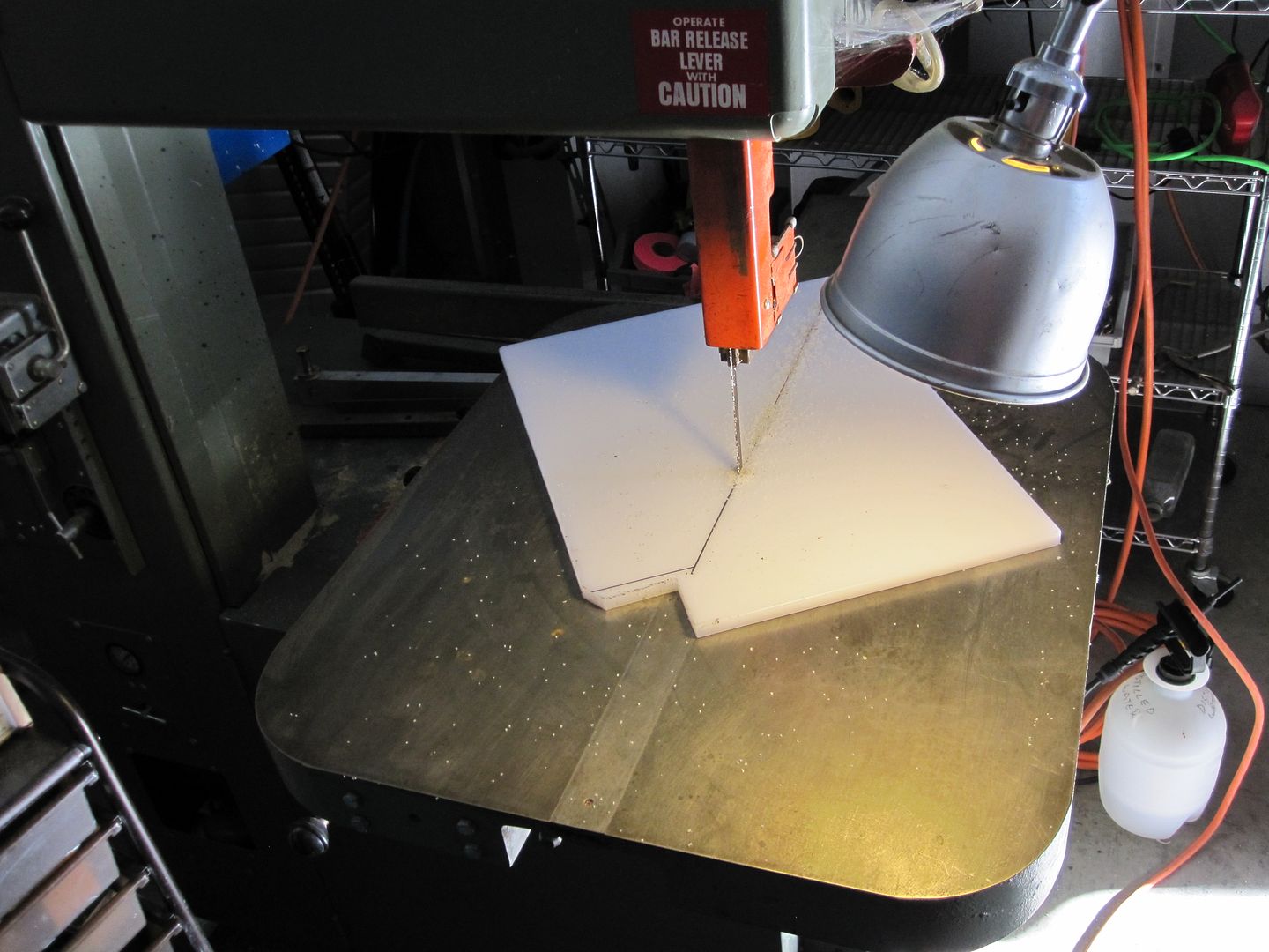
The saw is 208 3 phase and the Whisper Watt genny powers it nicely. |
|
|
|
[#22]
Quoted:
I suck at electric but did you get it to run at lower amps with a rheostat? How is that setup? Im a look/hear kinda persoin not a read/pictures. Got more info on this from yesterday's tests and will be doing more tests once I get all the sense cable stuff installed and hooked up. Stand by... |
|
|
|
[#23]
More about the field current. Last night and this morning I repaired a rheostat from ebay and installed it in the genny control panel.
It's a 25 ohm rheostat and seems to control the field current over the range I need it to. I was showing the system to a friend this AM and saw 90 amps out of the alternator into the system and that was with little load on the system and the solar panels putting about 50 amps into it by themselves! In the pix there's no knob on it and I'll pick one up if we go down tonight to shower and get some supplies. The power and sense cables from the genny connect to the barn like this. 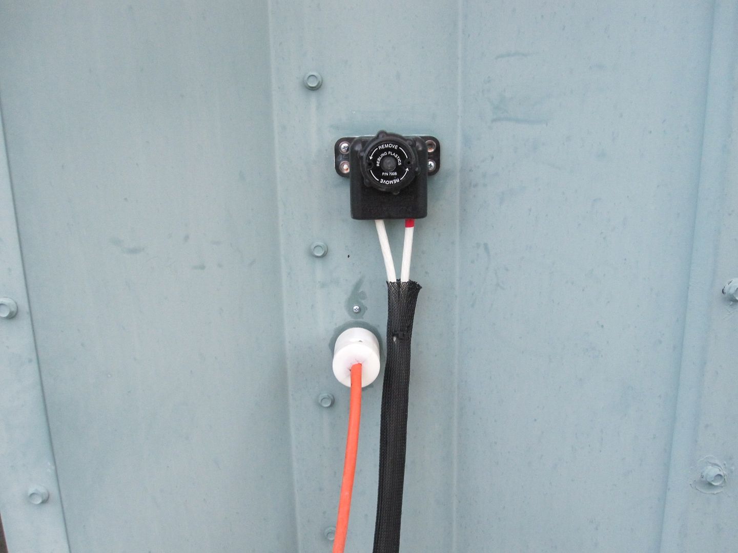
They connect to the genny like this as of yesterday... 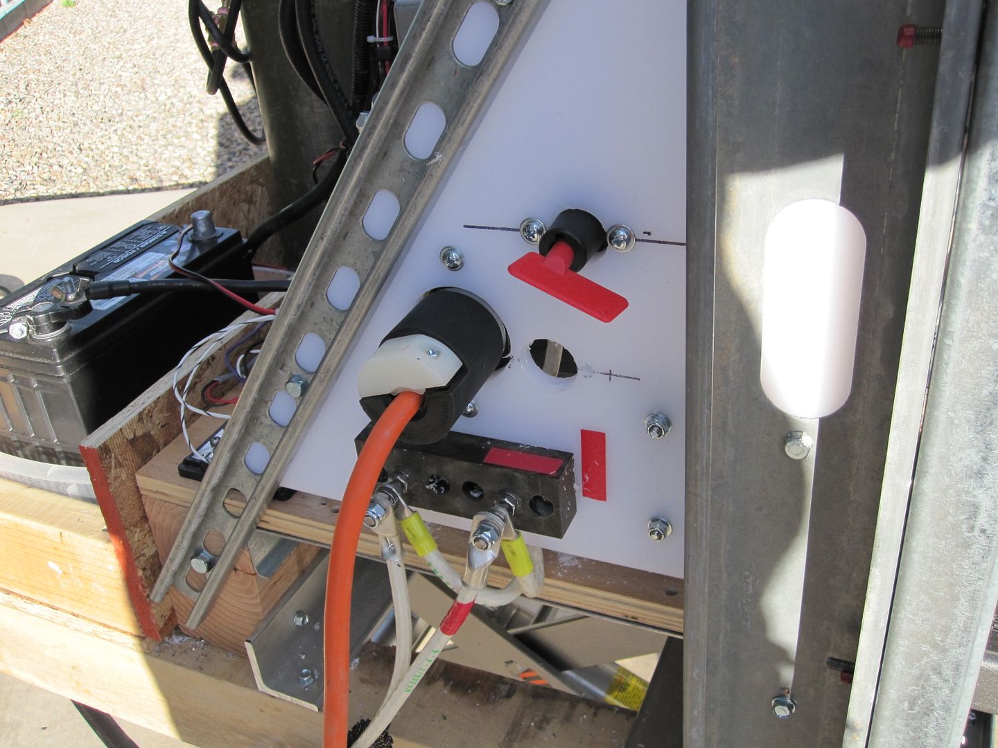
Today, the revised connection is like this with two threaded knobs to make it easier to attach/remove the cables. I might add an aircraft power connector like the one on the barn. 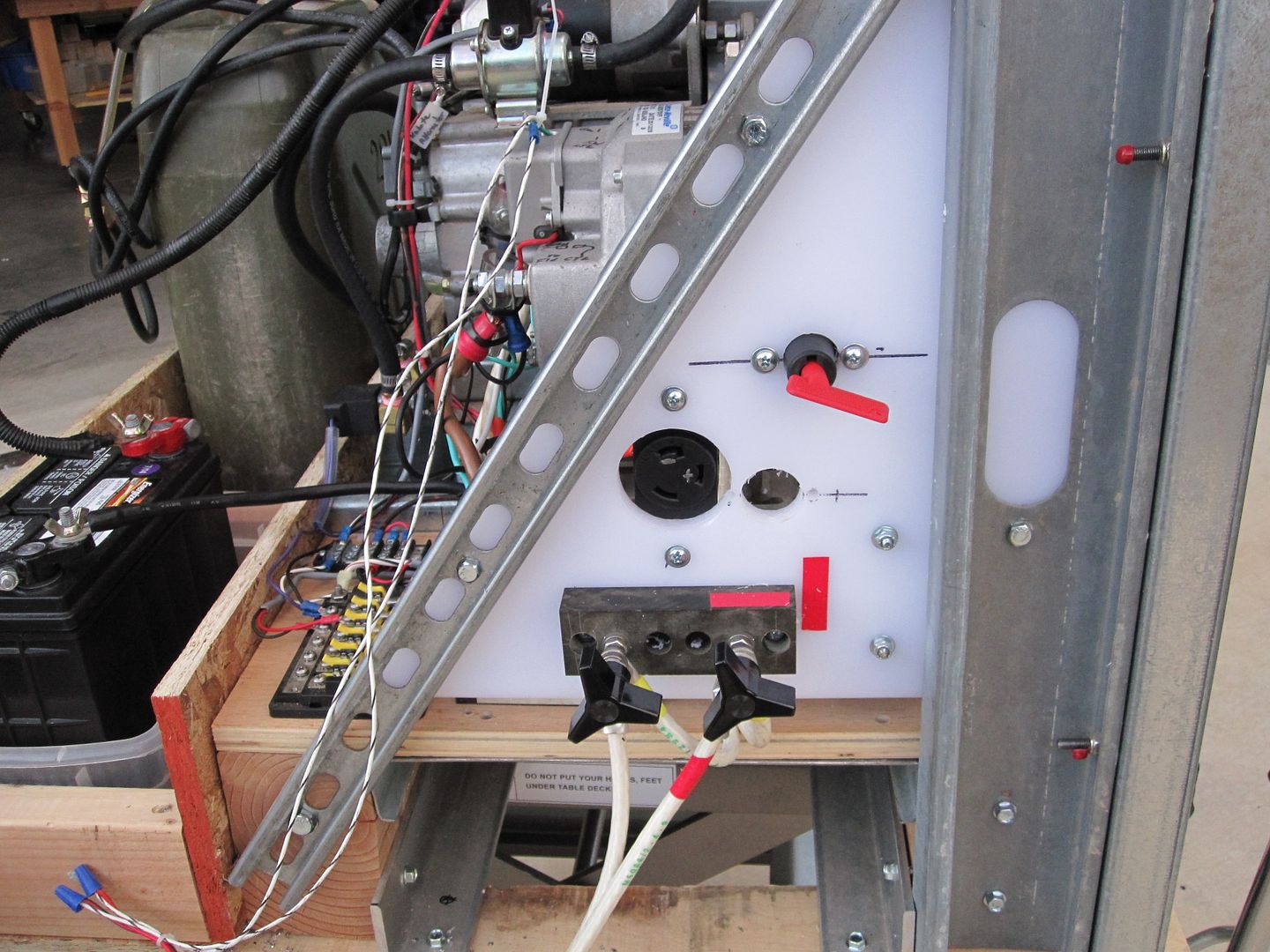
The money shot Genny running... 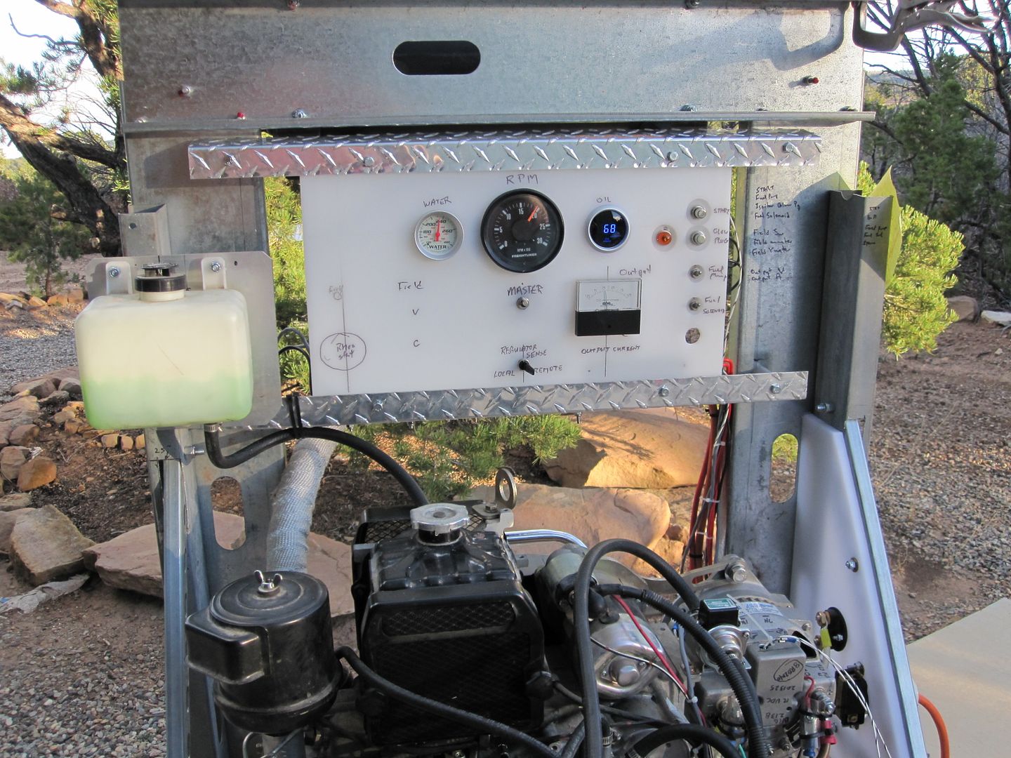
The Kubota loafing, the water temp get's to 240F. I wonder if this is too high? I verified the temp with an IR thermometer... The picture is from yesterday and doesn't show the field rheostat that was added last night... The rheostat connects to the two wires with the blue wire nuts. Engine is surprisingly smooth and quiet, not as quiet as a Honda EU2000 tho... |
|
|
|
[#24]
Oh, note the DPDT switch in the bottom center of the instrument panel.
It selects the sense voltage either "Remote" from the battery bank inside the barn ---via the orange wire, or "Local" from the terminals at the alternator. |
|
|
|
[#25]
Quoted:
Where would be a good place to find an engine like that ? Just saw one on ebay, looks iffy unless you are handy with these things. I'd ask if it was new when he bought it... |
|
|
|
[#26]
Discovered a way to increase the Leece Neville alternator output voltage to get more charge into the battery bank and also sufficiently high to equalize the bank.
This looks like the VR on the alternator I'm using -see other posts... 
The system as has already been described reached current limit cutoff around 14.7 volts, give or take a few 1/10's. I found that out the past week during a period of cloudy wx when the bank went pretty flat, so I went to the barn and put the Kubota alternator system to work. [Oh, to find a small diesel auto-start genny of abt 1000 watts, it looks like I will have to add this feature to the one I built] I charged the bank at about 90 amps from 4:45PM to midnight and only got the SG of the bank to about 1200 [using a temp compensated refractometer to measure] Target SG is at least 1260 for a well charged cell. When I hooked up the Kubota abt 11AM the next morning to continue the charge, the 3 solar systems were already putting about 40 amps into the bank and the voltmeter read 14.7 volts. Started the genny and it wouldn't provide any additional current to the batteries. [Incidentally, the 5 gallon Scepter fuel can was still about 1/3 full from the previous night's run, and previous runs, the system is very fuel efficient IMO] As mentioned in posts earlier, I had to add remote sense to the genny to reference its VR to the batteries ---connected near the batteries themselves. [Actually, I need to get a bit closer a few feet as at a charge of 100 amps, there is still a few tenth's voltage drop between the sensing connections and the battery terminals themselves. So, it appeared to me the solution to increasing the VR's effective cutoff was to place a power diode in series with the positive lead of the orange extension cable looking reference cable in the pix. I had a bunch of Schottky diodes at the barn with forward drop of ~ point 3 volts but needed more drop. Too lazy to series them... Finally found a humongous diode [ordinary silicon diode with .7 volts drop] maybe rated at 500 amps on a table, after an hour or so, and clipped it into the positive VR lead at the power dist panel after a 10 amp 3AG fuse.
That did the trick and now the genny easily put 90 amps into the batteries, the 3 Outbacks tapered off to only a light charge output, as would be expected, I guess, and the voltage [NEAR the sense connection] stabilized at 15.5 volts. Now before everyone who understands this jump all over me, I am familiar with US Batteries charge curves and charge voltage recommendations, and reviewed the link for their L16 batteries the night before ---while the genny was charging them. I will leave this here, those voltages seem to be a little low, even when new, I had to run closer to 16 volts to get good equalization that stabilized around 1270 SG. Even charging them when new, to about 15.5 volts [depending on temp, summer or winter] was needed to get a SG 1260. Don't axe me why my results differ from US Battery's recommendations.
Sticking with my procedure, since I like to achieve a SG charged of 1260. Unless someone offers a credible explanation of this process. Ran the genny for about 2 hours and something interesting happened... After abt an hour, I checked a cell from each of the 'sub-banks' and the SG had come up to ~1200 and 1220 respectively. Later I looked at a couple different cells and got SG discrepancies of as much as 40 points. I suppose that's why they need to be 'equalized' and these haven't been since last summer IIRC. Why? The highly insulated room and other nice to have loads, the two small chest freezers, all the networking and RF commo gear on 24/7, the IP cameras, lighting, the SHTF electronics lab, etc, etc, all take their toil on the solar harvested power. I will have to dip into my SHTF end of the world investment in solar panel trading stock and add more panels. So, back to the interesting finding... After running two hours, I noticed the charge VOLTAGE DROPPED to about 15.3 volts, yet the charge CURRENT was still happily at about 90 amps. All I can figure is that minor sulfation of the plates had been cleared to a degree and the batteries where accepting more current/charge, causing the voltage regulator to fall under its constant voltage setting [with the added diode] of 15.5 volts. So, I can't wait to get back there and continue the charge process [at the moment the batteries, after remote load shedding when I got home] are still showing 12.6 volts, better than in a long time. These batteries have been in constant use since abt 2010, one of the 'sub-banks' having been added a few months after the first. Will get back there in another day or so to continue the -hopefully- rejuvenation process. |
|
|
|
[#27]
I like this project op . My only thought is that look at a Delco Remy alternator instead of the Leece -Neville . I managed a fleet shop and the Leece-Neville had so much of a higher failure rate that the Delco that we stopped buying the Leece. The current Delco-Remy 24si rated at 150 amps in the same mounts as you are using are also reasonably priced compared to a Leece
|
|
|
|
[#28]
Quoted:
I like this project op . My only thought is that look at a Delco Remy alternator instead of the Leece -Neville . I managed a fleet shop and the Leece-Neville had so much of a higher failure rate that the Delco that we stopped buying the Leece. The current Delco-Remy 24si rated at 150 amps in the same mounts as you are using are also reasonably priced compared to a Leece I started out with the Delco, but trying to provide for connections to remote sense and general maintenance, like R&R the VR, I went with the L-N ---and have purchased backups. The brushes can be replaced on the L-N that I'm using in a couple minutes, and there are other maintenance features I like. So, I'm pretty much stuck.
|
|
|
|
[#29]
Forgot to mention, the current in the alternator's VR reference wires is ~2.2 amps.
Measured with a Fluke clip on ammeter, that are VERY marginally accurate at low current. I suppose a rheostat in series w/ the reference lead would serve to set the constant voltage, but I like the diode solution for accuracy. |
|
|
|
[#30]
Also wanted to mention, the ability of a cell to accept charge is partly determined by how many sulfur ions in the electrolyte.
As a cell 'sulfates' and forms insoluble sulfur compounds on the plates, sulfur ions are lost from the electrolyte and as the sulfation continues, eventually the electrolyte becomes just plain old water [sorta]. So, you can evaluate the aging of a battery by measuring its specific gravity when it is 'fully' charged. A lowering SG, for a given end charge voltage, suggests some sulfur ions have been lost from the electrolyte. Low SG electrolyte freezes at higher temps, explaining why we see batteries failing in the fall when ambient temps reach freezing. Something to think about [and measure] if you need your battery to work in a SHTF. See page two for electrolyte freezing points vs SG. Electrolyte freezing temps, pg 2 Here's a state of charge vs freezing point chart from Affordable Solar, I think. 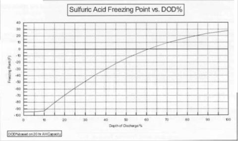
It's readily apparent that a poorly working vehicle charging system can lead to a damaged battery in not so cold wx. It's equally apparent, keeping tabs on your battery's SG with a hydrometer or refractometer, and charging system voltage with a Harbor Freight $4 DVM, could save you a breakdown... You do keep a DVM in your vehicle -dontcha? |
|
|
|
[#31]
bump for info for ongoing thread...
|
|
|
|
[#32]
240 seems a little high, isn't that about the boiling point of 50/50 ethylene glycol/water mix?
|
|
|
|
[#33]
Quoted:
240 seems a little high, isn't that about the boiling point of 50/50 ethylene glycol/water mix? Thanks for pointing this out JC. I looked at the radiator cap and it's rated at 16 psi. I think that may help out with the boiling point. The temperature sensor is right in the head near the exhaust and that's probably the highest temp location to measure it. |
|
|
|
[#34]
Not so good pix of the instrument panel with the new digital volt/amp meter.
It replaced the analog meter in an earlier pix. The meter is mt'd in a square of aluminum that is abt the same size as the analog meter with the same hole pattern. It's not running here, the amp readout is by blue LEDs. very hard to see, and I think I'll replace it again. 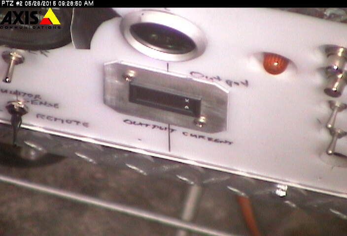
|
|
|
|
[#35]
For the techie guys here...
Something I found when working on this little diesel and a small spark ignition engine ---was that low cost Digital voltmeters go totally whacky due to interference from ignition systems. So trying to diagnose battery issues on spark ignition engines with a DVM could be impossible when the engine is running. I picked up a cheapie analog [old timey type with a pointer and scale] meter for about $10 at a box store. It works fine in the presence of the high tension ignition systems. Something to keep in mind. |
|
|
|
[#36]
Batteries have gotten run down for all the use we've given them, even with over 8 kw harvested many days.
So yesterday I fired up the Kubota/Leece Neville genset and started to get the SG up. [The gen-set works beautifully, and if anyone follows my footsteps, stick with the Leece-Neville alternator for MANY reasons... Stay away from the Delco's, been there done that... Right now between sun [clouds in and out] and the DC genny, they are putting ~150 amps into the battery bank. SG is abt 1260 right now. Talking with the [old-timey and brilliant] engineer who does their battery design, at US Battery a couple years ago, and referring to the info he gave me that I wrote on the wall at the batteries, he recommends charging to 16 vdc for equalization, every 2 weeks [I never do]. He also said to float to 15.5 volts in the summer and 15.6 volts in the winter, for 2 hours each day. |
|
|
|
[#37]
Something else...
The electrolyte level of the flooded batteries changes dramatically as they are heavily charged. I looked before starting this charge cycle while the SG was low. It looked like they needed water. If I HAD added water, right now they would be well overfilled. All the sulphur ions going back into solution in the electrolyte as the plate reaction goes forward, really swells the liquid. Be careful... |
|
|
|
[#38]
240 degrees is too high.
Diesel trucks generally run around 205 to 210. Could have a stuck/bad thermostat? |
|
|
|
[#39]
Quoted:
240 degrees is too high. Diesel trucks generally run around 205 to 210. Could have a stuck/bad thermostat? No there is no thermostat in this small engine. There is a radiator cap and it's good. The radiator and cooling asm is integral to the head. The service manual doesn't give a temp spec. Yesterday in the sun it got to 250F. That's at the hottest location in the head next to the exhaust port where the sensor well is located. Running fine, today too. The cooling system cap isn't blowing off or anything. Cap is rated at 16 psi IIRC. |
|
|
|
[#40]
Quoted: No there is no thermostat in this small engine. There is a radiator cap and it's good. The radiator and cooling asm is integral to the head. The service manual doesn't give a temp spec. Yesterday in the sun it got to 250F. That's at the hottest location in the head next to the exhaust port where the sensor well is located. Running fine, today too. The cooling system cap isn't blowing off or anything. Cap is rated at 16 psi IIRC. Quoted: Quoted: 240 degrees is too high. Diesel trucks generally run around 205 to 210. Could have a stuck/bad thermostat? No there is no thermostat in this small engine. There is a radiator cap and it's good. The radiator and cooling asm is integral to the head. The service manual doesn't give a temp spec. Yesterday in the sun it got to 250F. That's at the hottest location in the head next to the exhaust port where the sensor well is located. Running fine, today too. The cooling system cap isn't blowing off or anything. Cap is rated at 16 psi IIRC. |
|
|
|
[#41]
Quoted:
Seems darn hot, but a diesel is most efficient the hotter it is until she melts, so Quoted:
Quoted:
Quoted:
240 degrees is too high. Diesel trucks generally run around 205 to 210. Could have a stuck/bad thermostat? No there is no thermostat in this small engine. There is a radiator cap and it's good. The radiator and cooling asm is integral to the head. The service manual doesn't give a temp spec. Yesterday in the sun it got to 250F. That's at the hottest location in the head next to the exhaust port where the sensor well is located. Running fine, today too. The cooling system cap isn't blowing off or anything. Cap is rated at 16 psi IIRC. That's what I'm thinking... |
|
|
|
[#42]
There's a new [to me at least] digital DC voltage and current meter that measures high current -typically 100 or 200 amps...
And doesn't use a shunt. It uses some sort of toroid [I think on the same principles of DC clip on ammeters] that you have to pass the heavy current carrying inductor thru and these display current in both directions. I.e., charge discharge. Here's a pix from http://www.electronic-circuits-diagrams.com/store/img-large/dc-300v-0-100a-led-digital-voltmeter-ammeter-charge-battery-voltage-current-12v_281766909367.jpg 
The blue square thing in the picture is the current sensor. A lot of Sellers are offering these on eBay right now and I got one in the other day. The nice thing abt it was the price, only abt $12 or maybe 15, IIRC. Still haven't had time to hook it up and test it, but I'll report when I do. To find the various ones on eBay, need to search 'digital volt amp meter' and similar and look at the pictures until you see the blue sensor. |
|
|
|
[#43]
Quoted:
There's a new [to me at least] digital DC voltage and current meter that measures high current -typically 100 or 200 amps... And doesn't use a shunt. It uses some sort of toroid [I think on the same principles of DC clip on ammeters] that you have to pass the heavy current carrying inductor thru and these display current in both directions. I.e., charge discharge. Here's a pix from http://www.electronic-circuits-diagrams.com/store/img-large/dc-300v-0-100a-led-digital-voltmeter-ammeter-charge-battery-voltage-current-12v_281766909367.jpg http://www.electronic-circuits-diagrams.com/store/img-large/dc-300v-0-100a-led-digital-voltmeter-ammeter-charge-battery-voltage-current-12v_281766909367.jpg The blue square thing in the picture is the current sensor. A lot of Sellers are offering these on eBay right now and I got one in the other day. The nice thing abt it was the price, only abt $12 or maybe 15, IIRC. Still haven't had time to hook it up and test it, but I'll report when I do. To find the various ones on eBay, need to search 'digital volt amp meter' and similar and look at the pictures until you see the blue sensor. I think I need one or two of those..... |
|
|
|
[#44]
Quoted:
It uses some sort of toroid [I think on the same principles of DC clip on ammeters] that you have to pass the heavy current carrying inductor thru and these display current in both directions. see https://en.wikipedia.org/wiki/Hall_effect_sensor and https://en.wikipedia.org/wiki/Hall_effect_sensor#DC_current_transformers and especially see http://en-us.fluke.com/training/training-library/test-tools/clamp-meters/inside-hall-effect-clamp-meters.html ar-jedi |
|
|
|
[#45]
Interesting A-J...
|
|
|
|
[#46]
Nice build EXPY.
Any idea how much that engine and alternator assembly weigh's, minus the support structure? Thanks. |
|
|
|
[#47]
I think the engine is around 120# and the alternator is abt 20#...
|
|
|
|
[#48]
The new inexpensive DC digital ammeters are available in two current ranges on eBay for abt $15.
They measure simultaneously ---DC voltage and current. I got some of the 200 amp units in and will post a pix below of installed in the output lead the Kubota DC genny. Note the diameter of the opening in the current sensor, unlike the 100 amp version, the hole will easily pass at least #2 gage wire crimp terminals Notice the 3 wires that go from the display to the sensor. They'll have to be extended to remote and separate the 2 components, so the display can be mounted in the instrument panel. The 3 wires probably are for gnd, +5 vdc and signal, from an active circuit in the sensor. There's 2 potentiometers potted into the sensor and one is likely gain and the other offset, to calibrate the display amps' reading. I'm wondering about noise pickup... The red, black, and yellow wires from the display module, are for power source, ground [negative system] and sense wire [connected to anywhere where system voltage needs to be monitored. 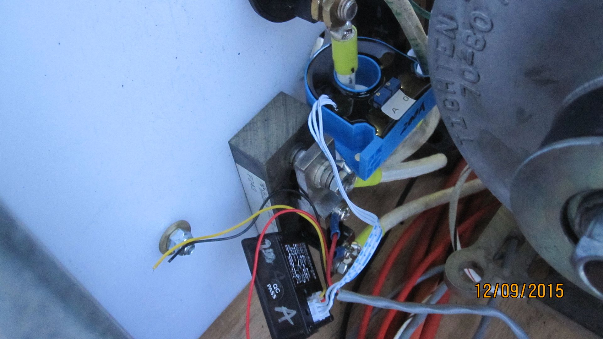
Something else that is really nice about these vs. most of the shunt based displays, is that the current can be read BIDIRECTIONALLY... I've got a 100 amp version connected to one of the main battery bank breakers, and same line has a shunt and display, and the readings are close. |
|
|
|
[#49]
EXPY your an inspiration!
|
|
|
|
[#50]
Haven't had the run the 4 HP diesel genny this winter to charge batteries ---since adding panels.
The panels we added have a more difficult time of shedding snow than the 4 original on the S end of the barn and the 3 on the container. They're sloped aggressively... The sun shines against the south bldg. end and heats up those 4 panels as the warm air rises, as well as the end of the container. Wx has been bad for a while and the batteries were running down, even with aggressive load shedding by remote control. The other day wx finally improved and the original panels saved the day at the barn. The night before the battery voltage under small load was 11.6 vdc at a below freezing temp, it was looking like a trip there was in the near future... In one day the 4 old 224 watt Sharp panels on the end of the barn put about 3.9 kw of juice into the batteries. Snow has melted off the other panels considerably, and they're adding a lot of charge too. I figger it will take 12kw+ to get the batteries in the barn topped off. So we can stay here working on projects and staying warm... Surprisingly, the batteries at the container didn't get nearly as low. For the folks who remember the solar box water storage system we built in ~2010, this year is the earliest I've seen it get very close to freezing, about 32.4F. Of course the phase change effect kicks in and there have to be a ton more BTU's exchanged to the outside before it actually freezes hard. After the wx got better, the temp has been going up according to the sensors. Water is close to 40F now, and that's ~120 gallons because SO filled the tank before winter set in. An issue we've always had is the snow falls off the 3 container panels right onto the solar box glass.
|
|
|
 Win a FREE Membership!
Sign up for the ARFCOM weekly newsletter and be entered to win a free ARFCOM membership. One new winner* is announced every week!
You will receive an email every Friday morning featuring the latest chatter from the hottest topics, breaking news surrounding legislation, as well as exclusive deals only available to ARFCOM email subscribers.

AR15.COM is the world's largest firearm community and is a gathering place for firearm enthusiasts of all types.
From hunters and military members, to competition shooters and general firearm enthusiasts, we welcome anyone who values and respects the way of the firearm.

Subscribe to our monthly Newsletter to receive firearm news, product discounts from your favorite Industry Partners, and more.
Copyright © 1996-2024 AR15.COM LLC. All Rights Reserved.
Any use of this content without express written consent is prohibited.
AR15.Com reserves the right to overwrite or replace any affiliate, commercial, or monetizable links, posted by users, with our own.