|
Posted: 10/22/2014 12:30:33 PM EDT
The solar power distribution arrangement in the barn has evolved but is sort of messy.
Here's a pix at the more recent stage of evolution... Circa 2012... 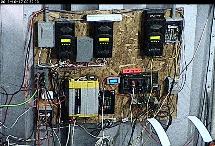
It's been in service since abt 2009 and has performed very well. The complexity has just increased over the years and with the 4HP Kubota alternator for charging the battery bank almost ready, I thought it would be a good idea to clean up things a bit, especially to help with a more elegant means to connect the alternator to the battery bank. Here's the battery bank... 8 L16 batteries in 2 banks of 4 connected in series\parallel with an output of 12 vdc. It's easily reconfigurable to 24 volts, however, I have reasons to stay at 12 volts for the moment. It's very clean now and presents well... Not nasty like in the pic. Note how the batteries rest on pink foam insulation that is rumored to prevent the concrete floor from sucking charge out of the batteries... 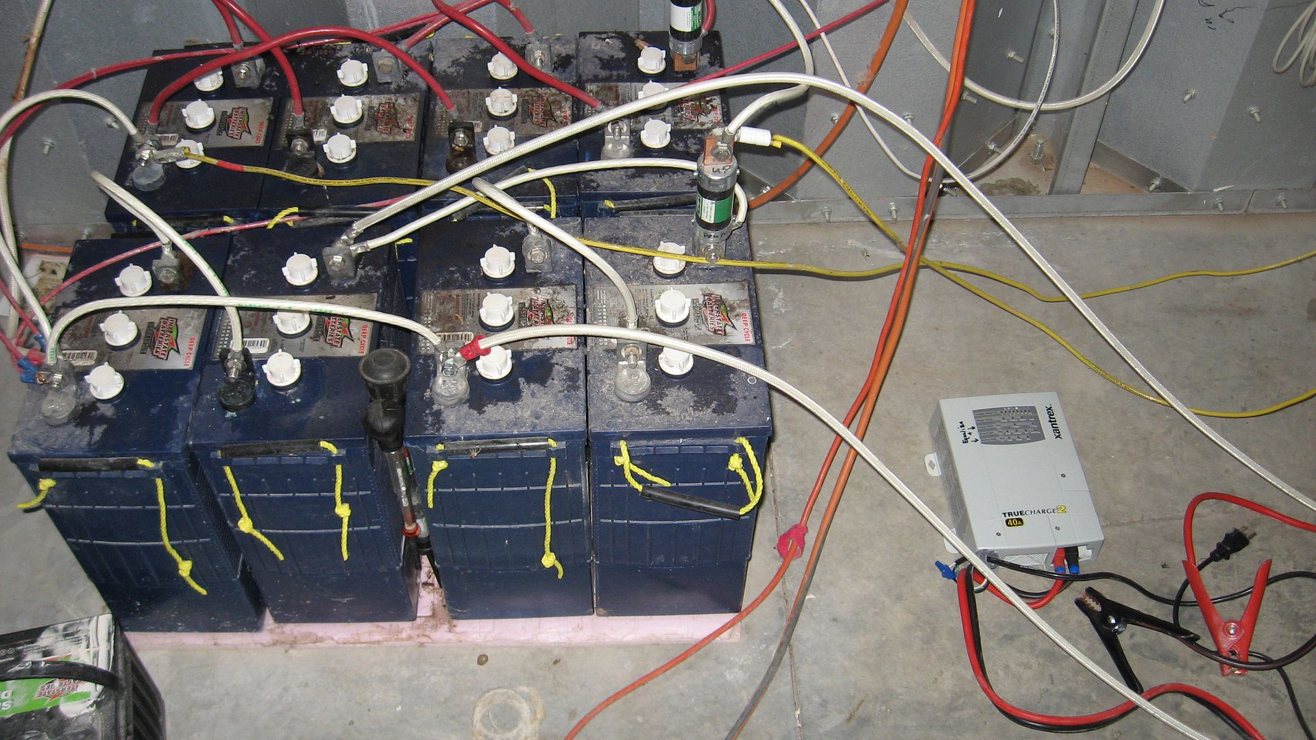
The little charger on the floor is a Xantrex TrueCharge 40 amp with a line cord and Harbor Freight battery leads connected to it. We have two of them and when the sun isn't shining well, can connect them simultaneously directly to the batteries bank and put 80 amps into the batteries running off the light-tower or the Honda 2000. These are nice chargers and can be set to provide a higher than normal charge voltage to do equalization. |
|
|
|
[#1]
Notice in the pic of the batteries that all the devices in the system are connected directly to the battery or to the 2 fuses on the negative terminals
of the 2 banks. In other words all the power distribution connections are at the terminals of the batteries, this works well ---up to a point of complexity. So, in the pix to follow, I'll change the wiring so the devices connect to a 1920's style 'switch board' upgraded to 'modern' tech. 
|
|
|
|
[#2]
Here's where I start planning how I'm going to lay out the various circuit protection and interconnection stuff.
You will notice that I use special BPA Free switch-board panels from WalMart. They measure abt 20 x 15 inches. 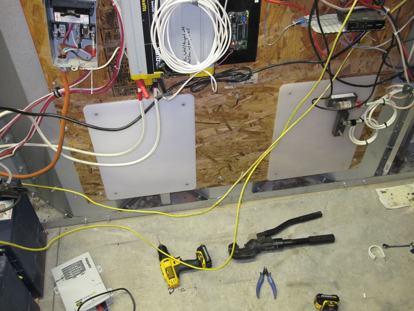
Note the circuit on the far right where I've already built the initial connection for the Kubota alternator input. Kubota alternator -early pix that doesn't show revisions... For charging batteries when power consumption exceeds solar harvest. 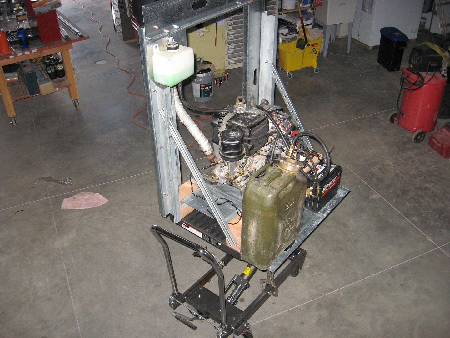
Here's a close-up of the circuit that will have a blocking diode and high current selector switch added later. Note the special fuse I wrote abt in another thread on solar power systems... 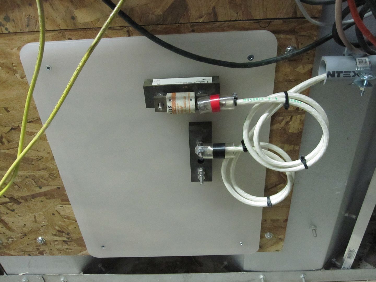
Years ago, maybe in the late 1980's at the Dayton hamfest, someone had 2 full cable spools --the kind that are so big you can't lift them, of aircraft 2 and 4 gauge wire. ~1000 feet per spool... The cable is of high quality with a zillion fine strands so very flexible. I didn't know exactly why then that I bought them both, but I did for abt $150. Anyhow, note how I use 3/4" ID vinyl tubing cut just so as terminal protectors. The cables from this interface go to the right in 1 1/2 inch conduit over a man-door and down the other side and terminate in a high current aircraft battery connector. The genny connects to it with a fancy mating connector that I'll show more detail of later in the Kubota thread. |
|
|
|
[#3]
That looks like something MacGyvers mentally handicapped 7 year old wired up.
|
|
|
|
[#4]
Quoted:
That looks like something MacGyvers mentally handicapped 7 year old wired up. Well! I'm VERY proud of it...
You should have heard what SkiBane said when he first saw it years ago. It isn't printable by my dainty finggers... |
|
|
|
[#5]
Lol
At least you know it isn't pretty and you are doing something about it. I think we have all wired something up that could use an overhaul. I think time/budget rolls into how pretty something can be. Good luck with the project! Quoted:
You should have heard what SkiBane said when he first saw it years ago. It isn't printable by my dainty finggers...
Quoted:
Quoted:
That looks like something MacGyvers mentally handicapped 7 year old wired up. You should have heard what SkiBane said when he first saw it years ago. It isn't printable by my dainty finggers...
|
|
|
|
[#6]
Here's a layout of the panel using fuses and buss bar ---just trying out ideas...
The arrangement allows another battery bank to be added later. 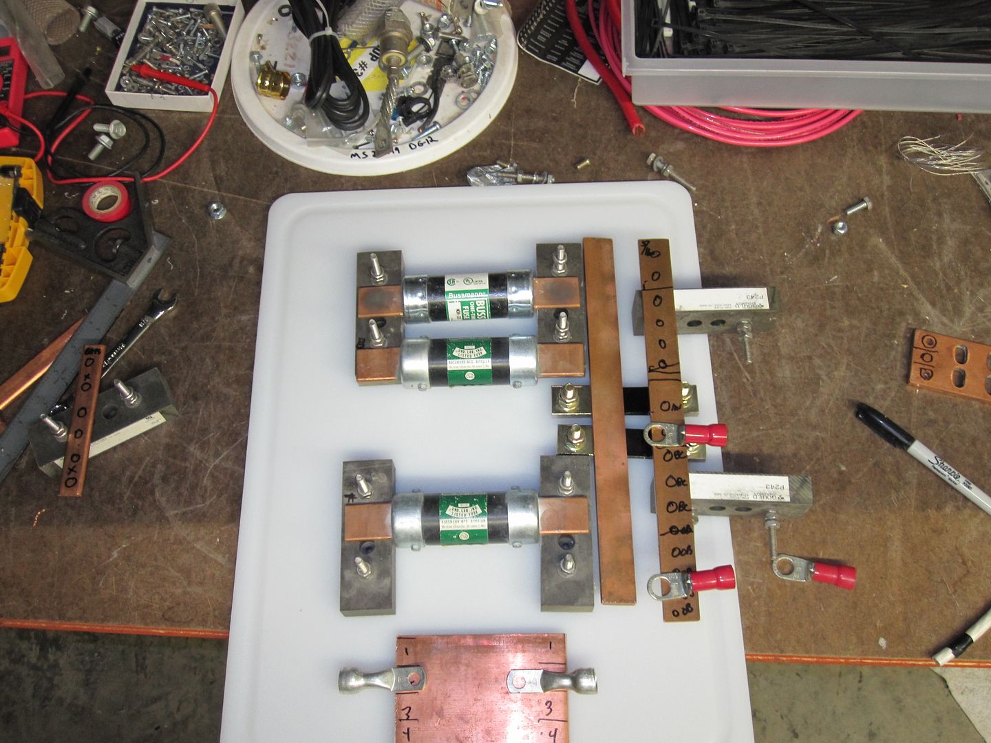
Some years ago, I bought a big box full of those Gould fuse holder blocks, that can be adapted to many versatile purposes, by cutting, and retapping for different size studs, etc. You will see extensive use of them... The fuses didn't get used, instead I used some circuit breakers I found at a hamfest abt 2009. At 12 o'clock in this pix there's a big diode I'm thinking abt putting in the circuit from the alternator charger. It isn't a Schottky tho... Date code is from 1979... |
|
|
|
[#7]
The diode.... has no business in the charge circuit.
the Leece Neville alternator pictured 6 diodes, quite enough enough for the purpose.
|
|
|
|
[#8]
Quoted:
The diode.... has no business in the charge circuit.the Leece Neville alternator pictured 6 diodes, quite enough enough for the purpose. You make a good point. I was looking at them yesterday while adding the UHDP side panel for the power connection to the cable that plugs into the building outside, a shunt, fuse, etc, and was wondering if they would do everything needed. |
|
|
|
[#9]
Changed my mind about using the big fuses [the same kind that were previously used on the neg terminal of the 2 battery groups as shown in the pix]
And decided to use some big circuit breakers I picked up cheap years ago. They are on the left switch BPA free panel. There's two shunts [for analog or digital readout of current flowing from either/or battery groups] on the buss bar on the right side of it... All power distribution in this picture is from the terminals of the batteries and fuses. Works fine, but messy and little room for expansion. 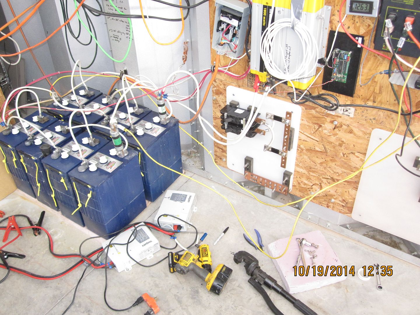
Buss bar on the right side of the panel will be for Positive power distribution. Buss bar horizontally across the bottom of the panel is for ground/common/return/etc. The system is now over-current protected in the positive side vs the old system with fuses on the negative side. |
|
|
|
[#10]
Here's the batteries all cleaned up -Thanks SO!
The fuses have been removed as well as all the ancillary wiring and connections and just the 2 gauge wires are going to the breakers. The first thing to do now is make sure to test the breakers -since they are the only circuit protection form the batteries tremendous instantaneous current capability. 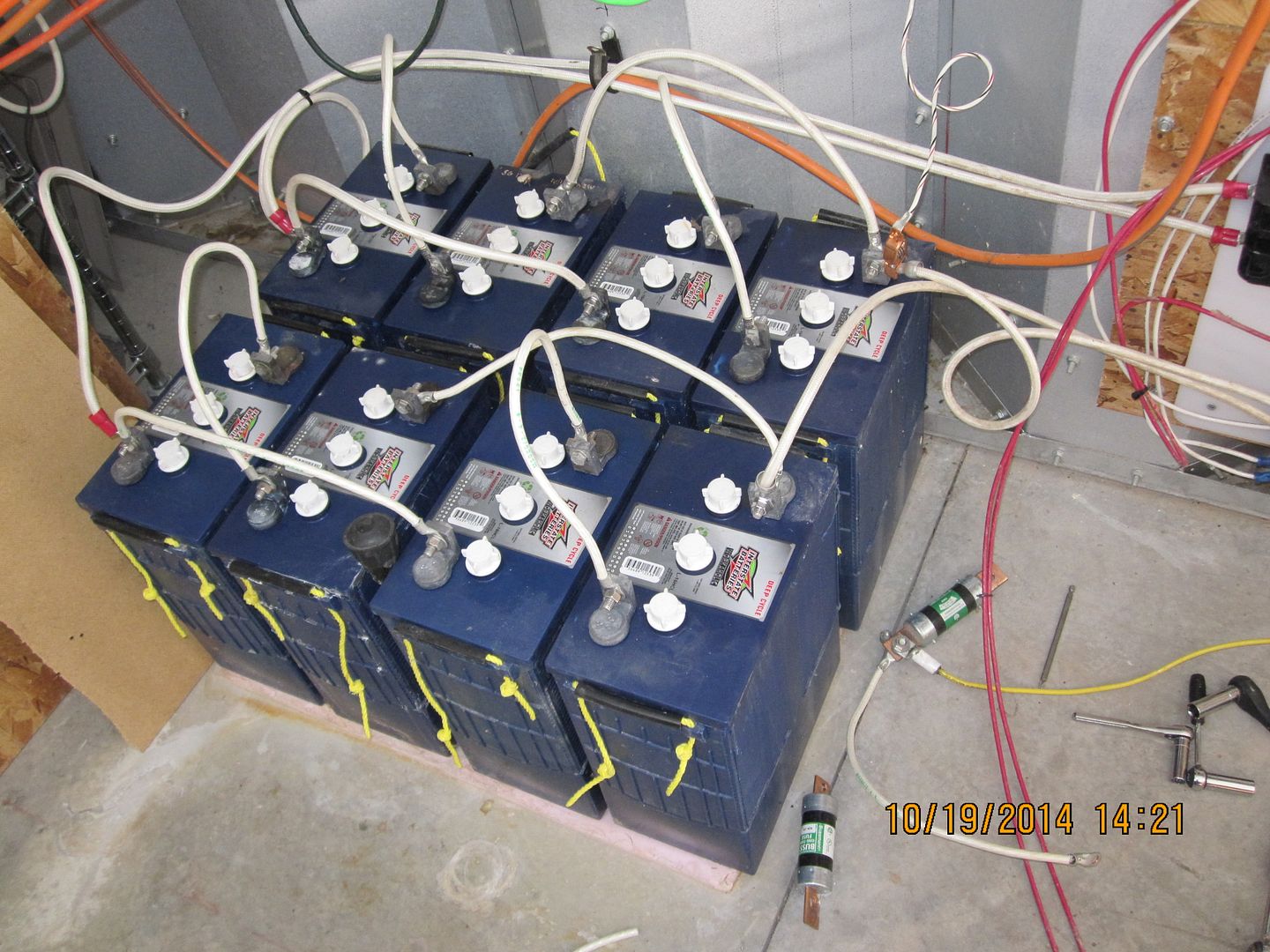
Removed fuses that have served well for years, are on the floor... RIP fuses... |
|
|
|
[#11]
The buss bars were easy to fab from 1 inch or so wide thick copper stock from ebay.
Upper one is drilled and tapped for 3/8 x 18 bolts. And a few 5/16 bolts and some 1/4" holes for mounting using the versatile Gould fuse blocks -that I will use for all sorts of purposes in following pix. The copper material is a little gummy to work with but I was able to fab the bars much more quickly than I thought... |
|
|
|
[#12]
Time to do the crowbar test on the breakers to make sure they trip under high current loads.
My SO had to use the crowbar because I had something else to do right then... She said they tripped OK. 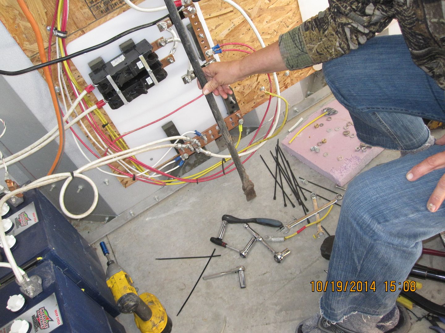
Afterwards she fixed me a sammich! |
|
|
|
[#13]
As usual in projects like this, some things have to be changed, on the fly.
So instead of using the same big pecker sized fuses, it seemed like big fat circuit breakers would work out better. Here's the latest revision of the power distribution panel... 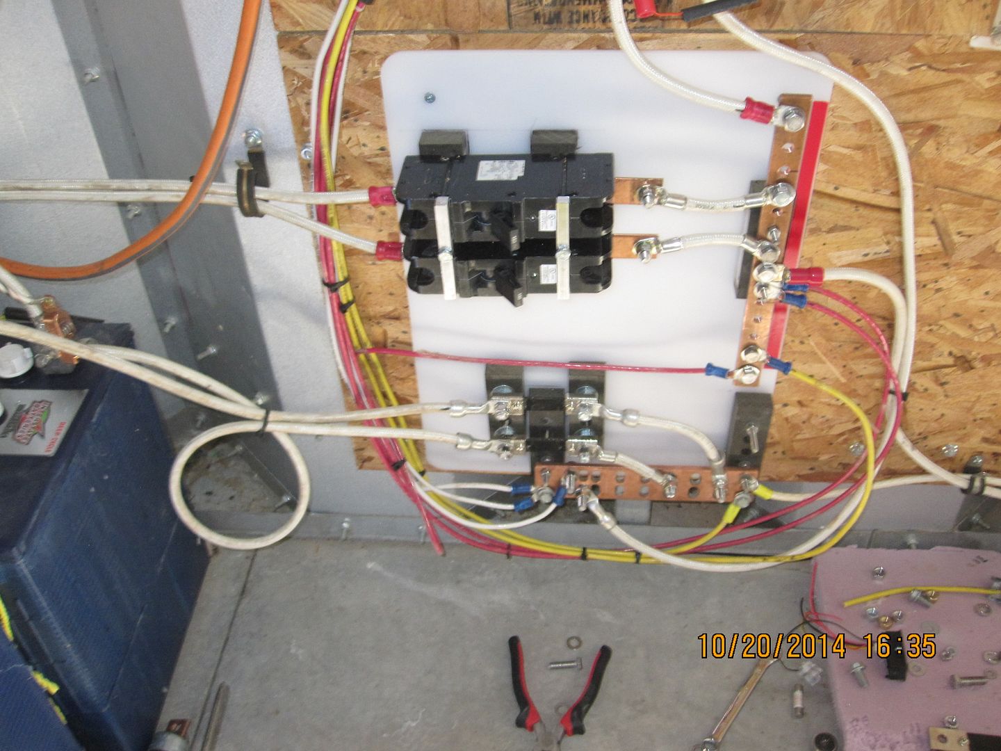
Note that the 2 shunts have been moved to the ground side of the system, they are at the bottom of the panel in series with the 2 negative cables from each of the 2 groups of batteries. There are 2 small Phillips screws, one on each side of each shunt that connect either to a millivolt meter or to a digital readout. The advantage of the meter is it uses no 'power' to operate. The digital readouts use maybe 100 ma at 12vdc power and are bright and nice to look at. For portable equipment, like an Emcom box, this might be unacceptable and maybe a push to read should be incorporated to save power. |
|
|
|
[#14]
Here's the best and fastest way I've found to modify big heavy terminals -or even smaller ones, to fit the size screws you are using, without having to buy a whole bunch of different ones with different holes and wire gauge sizes.
A small impact driver works better than a drill and the step drills are cheap at Harbor Freight, one of the great values there. We've used these step drills in 14 gauge steel and they had a great service life, enlarging countless holes for the building. 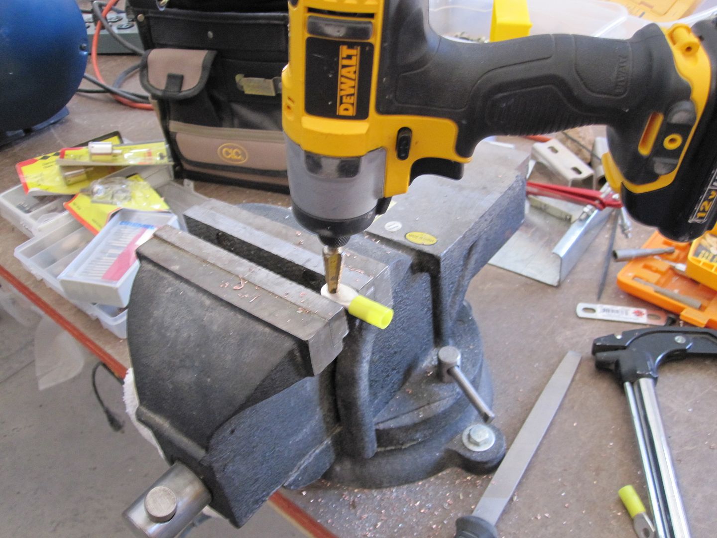
|
|
|
|
[#15]
The past few days have been busy making the hopefully final revisions of the power distribution panel and additional work to the Kubota/alternator genny.
The pix below shows a general overview of the barn solar and aux power system as of roughly today. There has been some sense ckty added on the right panel with more details below. The UHDP panel on the right has the stuff needed to switch the Kubota engine-truck 12 vdc alternator into the system into the batteries to charge them AND to power the devices and appliances in the barn when the sun's not shining too good. Look how much 'cleaner' the system looks vs the picture in the first post above... 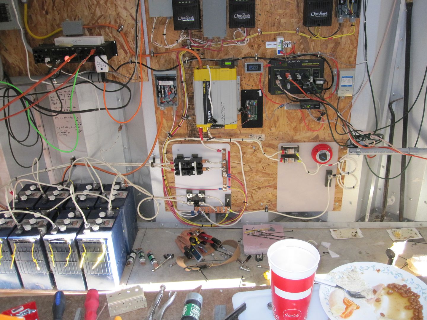
The next pic shows the alternator to battery interface. There's a fish tape sticking out of the 1 1/2" conduit to pull 2 white #12 wires thru it to near the wall outlet where the 12 vdc from the genny comes into the building. One of the wires goes to the negative buss below the selector switch and the other goes thru the fuse and to the common operating point of the switch. When the switch is 'off', there's no connection of the positive sense wire to the battery bank. The selector switch allows charge to be directed to battery bank one or two, or both. The alternator had to sense the voltage at the battery bank because there was to much voltage drop, even thru the #4 and #2 wires between it and the panel, and the alternator output voltage never got high enough under load to get much charge into the batteries. Now, with the alternator sensing the voltage within a few feet of the batteries it can easily provide a charge current of at least 90 amps into the batteries at 2000 RPM. My goal is to run typically 80 amps out of the alternator. 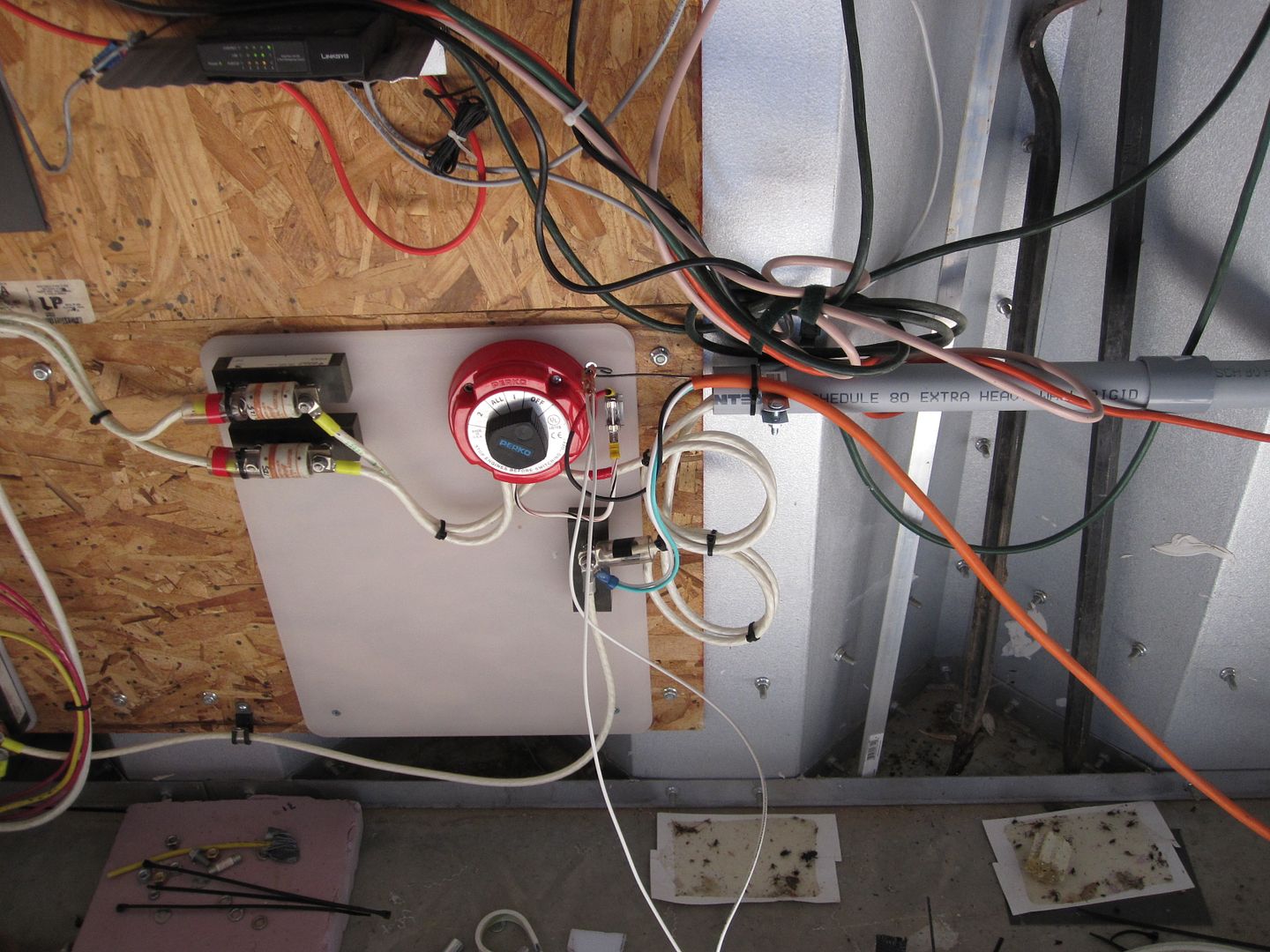
|
|
|
|
[#16]
Here's the outside of the barn where the high current 12 vdc comes in and the plug and orange wire is the 'sense' connection between the alternator and the battery bank.
These cables run to the Kubota/alternator, outside. 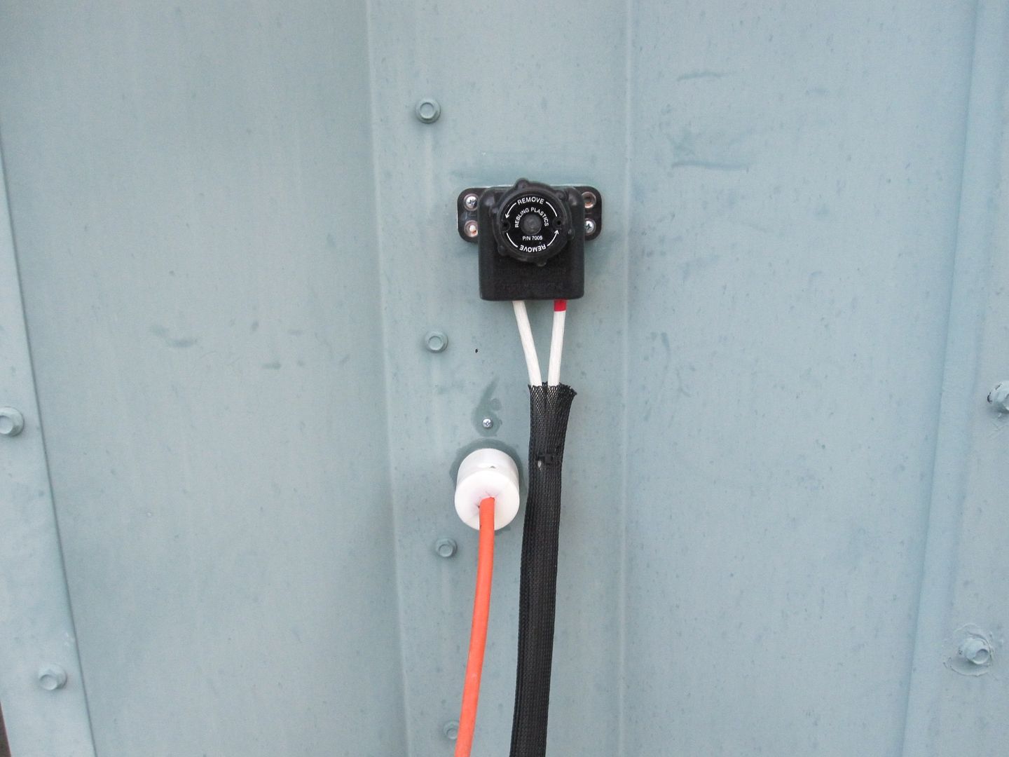
|
|
|
|
[#17]
I'm curious are you using a truck engine to power just an alt and not a generator head? Seems like there is a lot more charging potential than what you are using from the engine.
|
|
|
|
[#18]
Quoted:
I'm curious are you using a truck engine to power just an alt and not a generator head? Seems like there is a lot more charging potential than what you are using from the engine. Engine is abt 4 HP. Answer |
|
|
|
[#19]
I went through the same things a few years ago. First install had wire kaboblations everywhere. I went through and where I could, snaked wires through blue flex tubing and in general "cleaned up" the install.
Don't worry too much about how it looks, worry more about how it functions and the safety. Those that don't actually have systems are usually the first to criticize. I guess in Mommy's basement all the wires are run all neat and tidy ;) |
|
|
|
[#20]
Yesterday there was some heavy current flowing thru the breakers and the internal contact resistance/voltage drop across the breakers could be measured.
The top breaker that originally had IMO too much contact resistance and I drilled and sprayed with some sort of contact cleaner has settled down to a very low contact resistance, something like 30 millivolts at 40 amps. Opening and closing the breaker doesn't change it like before the 'treatment'. The lower breaker that I thought was pretty good was worse than the top one, so I took them all loose and drilled the 2nd one and mounted it on top so I can access the hole if need be. It immediately improved and I'll check them again today. I think from the date codes and appearance that these are pretty old and might not have been used and the silver alloy the contacts are likely made from became corroded ---not just oxidized, [silver oxide is a good conductor] I think I have a couple more of these, just need to find them and if I can might drill out the rivets and look inside. Heinemann has been bought out by Eaton after having been making literally countless breakers for everything imaginable. They started IIRC reading in 1939 and probably were an important WW2 resource. The breaker I'm using is the GJ1 series, rated for 100 to 1000+ amps. I searched and can't find any reference to contact resistance. As I expected this breaker series has a bimetallic trip that operates on significant rise of temperature. However, the main operating factor is current passing thru a winding of maybe 10 or so turns that act as an electromagnet to operate a leveraged trip mechanism. Some of these models have some sort of 'hydraulic' time delay that I haven't been able to find info about and don't understand. My guess is there's a bellows chamber and an orifice inside the chamber to limit how fast it can expand or contract. Here's a pix of the first CB that I 'cleaned'. 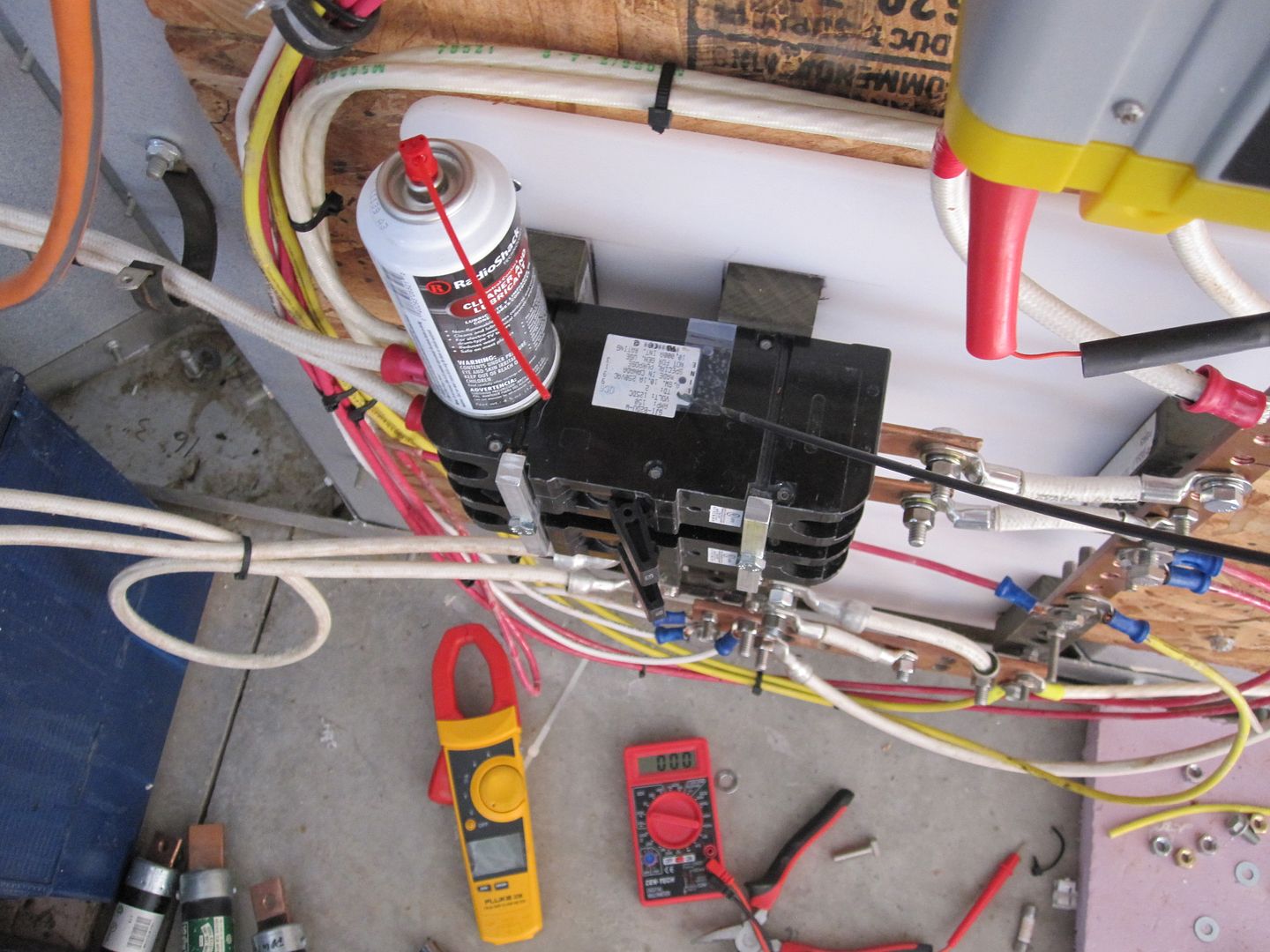
|
|
|
|
[#21]
Incidentally, no matter what size solar system you build, it's useful to pay attention to the power wasting series resistance in the wiring, across switches, circuit breakers and fuses.
The simplest way to check this is with [even a $4 Harbor Freight DMM works superbly] a digital or analog volt meter on the millivolt scale. Each location where wires are joined mechanically together is useful to check and pretty soon you will get a feel what is acceptable and not. On bigger systems, it's often enough to feel each fuse and connection for temperature rise. That's how I first noticed the loss in the CB, I routinely felt it under load and noticed it was slightly warm. The fuses in say the Outback protection on their output , in the case of the FM80, pass at times 50 amps and get very warm. Frankly, on the previous disconnect box [on the top far right next to the Outback, the clips that hold the NON-60 fuse got so warm they corroded or something and ran away and burned out the fuse. So I replaced the disconnect box with Square D and it's been in service abt two years. The previous disconnect on inspecting was designed poorly. I'll probably replace all the fuses in those disconnects with circuit breakers in the next panel revision. Fuses inherently waste power because they have to get warmer and warmer as current increases and the resistance of the fuse element reaches a point where sufficent temperature rise melts it. All this process wastes power. Magnetic operated CB avoid much of this power loss because they work on the aforementioned magnetic trip, very little power is used to cause the breaker to trip. SO magnetic trip CB's ---NOT the THERMAL trip type ---are the choice for good efficiency. |
|
|
|
[#22]
Circuit breaker story...
I worked for a LARGE computer company as a kid and one of my accounts was a big pharma co that everyone would recognize. They had several big mainframe systems and one was getting I/O failures and in those days when they locked up a days worth of work could be lost and the downtime cost could approach a $100 Grand. So it's understandable they got pissy re downtime and we had to provide 24/7/365 support of top notch quality for extremely complex systems. Anyhow this customer was having issues and I got my first learning experience with circuit breakers while wet behind the ears. For some reason I walked to their electrical distribution area and just felt the breakers and one was HOT. It turned out that it was one of many serving the failing system. I went to the DP manager and showed him and suggested they replace it. Happy customer! No more failures. ETA- The DP manager's wife became my accountant and [sort of one of my mentors] when I started my company... The company is STILL my accounting firm many decades later... |
|
|
|
[#23]
Both circuit breakers I cleaned are still doing great!
|
|
|
|
[#24]
bump for info on ongoing thread...
|
|
|
|
[#25]
To help educate Desert_AIP
|
|
|
|
[#26]
It may just be me but service loops on high power/current lines make it hard to look at the pictures. Is there a reason you are using them? I would use rubber boots or some of that tubing you have to cover the terminals too.
Thanks for posting your system, I love reading about these. I'm currently grid-tied solar but will eventually have a battery backup tied in for essential circuits. |
|
|
|
[#27]
Quoted:
It may just be me but service loops on high power/current lines make it hard to look at the pictures. Is there a reason you are using them? I would use rubber boots or some of that tubing you have to cover the terminals too. Thanks for posting your system, I love reading about these. I'm currently grid-tied solar but will eventually have a battery backup tied in for essential circuits. Thanks Ron. The battery interconnection loops are longer than what is probably normally found because my loads aren't often that great, and I2R losses are quite manageable [system efficiency] due to the available sun and number of panels. Loads tend to be security, electronic, lighting, and 2 small chest freezers. Typically I don't see more than 30 amps drawn from the bank for a few minutes unless I turn on a bunch of lights or the spectrum analyzer and other test equipment in the lab. I'm using #2 or #4 aircraft hookup wire [bought 2 ~1000 foot spools in the 1980's at Dayton Hamfest without having any idea it would come in so useful] that's lighter than what's commonly used. If the losses ever become an issue, I'll get larger terminals and run a pair of #2's in parallel. There are some locations I put vinyl tubing or other insulating media over connections, I just don't do it at the batteries, altho it's best to do so. I'll likely take your advice and shorten up the battery interconnects in the future and double up the #2 cables to the inverter and to the CB's. Also, sometimes I put on a heavy load and survey the connections with an IR viewer. Found a number of issues this way. The Outbacks have been in service for many years and I'm expecting to start getting 'high' resistance joints on the high current solder joints of the internal PC boards [that will likely be easily repaired] Surprised it hasn't already happened... You might like this thread abt a 4 HP diesel that charges this system a few times per year or when heavy loads are run for some time. I plan on adding digital voltage and current readouts to the genny control panel in the next few days once the optical fiber install is finished and a bunch of roof bolts are sealed from leaks, and will update the topic. Here |
|
|
|
[#28]
Here's a digital volt amp meter connected to one of the 2 battery banks, or the upper shunt in preceding pix.
The issue with this olt amp meter is it only reads current in one direction, depending upon how its two shunt wires are connected. If they are reversed, current flowing INTO the batteries is measured. Right now, they're connected so current flow OUT of the batteries is measured. Ebay IIRC had some digital meters that read current in both directions, but I can't find them. There are cheap abt $8 incl the 200 amp shunt. I like using plastic electrical boxes to make enclosures for the meters and cut metal panels to the meter. 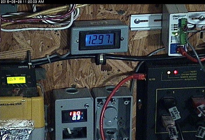
|
|
|
|
[#29]
Here's something that might be useful for folks running Ethernet cabling close to high frequency power switching devices like inverters, charge controllers, etc.
Like the pix above. I had some issues with Ethernet cables to IP cams both possibly picking up noise and also radiating RFI and interfering with receive antennas in the 50 and 150 MHz bands, and others I'm sure. I tried some of those 'clip-on' ferrites on Ethernet cables to suppress noise picked up near an Outback controller, without success. The other day I found some big toroids almost 2" in dia w/ a one inch hole, colored red and marked T184-2, that I had left over from designing a lightning tracking device years ago. Exactly like this down to the packaging: h+(Q~~_35.JPG)
4 turns of Ethernet cable with the connector installed can be easily `wrapped on the core, even more if you start without the connector. To see how well these suppressed noise, I did a test with an antenna connected to a 150 MHz receiver placed near an IP camera and about 30 feet of wire to a network switch. The receiver picked up all sorts of squeaks and squeals and when the network cable was unplugged from the switch the noise disappeared. Then a toroid was installed on the cable at the switch w/ 4 turns and it didn't make any detectable difference. A toroid was installed the same way at the camera and the noise was greatly reduced. Using the squelch control as a means to measure the difference, it only takes a tiny rotation of the control to squelch vs the camera unplugged at the switch. If you can find some old surplus or junk inverters, switching battery chargers like the Vector, etc, similar ferrites can be harvested at little cost. |
|
|
|
[#30]
Subscribed!
|
|
|
|
[#31]
Utility background here. power substation control room battery banks 48 v 110-220 ah, ( one location 110 V. 200 AH monster), I have worked around have breaker panels using both of legs of the breaker (our system used square D) neutral and hot through the breaker. High fault current rated breakers industrial grade, larger than home grade. Also the neutral was isolated from the ground, charger monitored for a grounded neutral and grounded hot. You done any research into DC power breaker applications?
Also had to use earthquake rated battery racks. Quoted:
As usual in projects like this, some things have to be changed, on the fly. So instead of using the same big pecker sized fuses, it seemed like big fat circuit breakers would work out better. Here's the latest revision of the power distribution panel... http://i994.photobucket.com/albums/af66/expy37/mountonwallforKgen182_zps6482c4f5.jpg Note that the 2 shunts have been moved to the ground side of the system, they are at the bottom of the panel in series with the 2 negative cables from each of the 2 groups of batteries. There are 2 small Phillips screws, one on each side of each shunt that connect either to a millivolt meter or to a digital readout. The advantage of the meter is it uses no 'power' to operate. The digital readouts use maybe 100 ma at 12vdc power and are bright and nice to look at. For portable equipment, like an Emcom box, this might be unacceptable and maybe a push to read should be incorporated to save power. |
|
|
|
[#32]
Thanks for the info and progression of the project.
I only wish I had the time to experiment with something like that. |
|
|
|
[#33]
Quoted:
Utility background here. power substation control room battery banks 48 v 110-220 ah, ( one location 110 V. 200 AH monster), I have worked around have breaker panels using both of legs of the breaker (our system used square D) neutral and hot through the breaker. High fault current rated breakers industrial grade, larger than home grade. Also the neutral was isolated from the ground, charger monitored for a grounded neutral and grounded hot. You done any research into DC power breaker applications? Also had to use earthquake rated battery racks. Quoted:
Utility background here. power substation control room battery banks 48 v 110-220 ah, ( one location 110 V. 200 AH monster), I have worked around have breaker panels using both of legs of the breaker (our system used square D) neutral and hot through the breaker. High fault current rated breakers industrial grade, larger than home grade. Also the neutral was isolated from the ground, charger monitored for a grounded neutral and grounded hot. You done any research into DC power breaker applications? Also had to use earthquake rated battery racks. Quoted:
As usual in projects like this, some things have to be changed, on the fly. So instead of using the same big pecker sized fuses, it seemed like big fat circuit breakers would work out better. Here's the latest revision of the power distribution panel... http://i994.photobucket.com/albums/af66/expy37/mountonwallforKgen182_zps6482c4f5.jpg Note that the 2 shunts have been moved to the ground side of the system, they are at the bottom of the panel in series with the 2 negative cables from each of the 2 groups of batteries. There are 2 small Phillips screws, one on each side of each shunt that connect either to a millivolt meter or to a digital readout. The advantage of the meter is it uses no 'power' to operate. The digital readouts use maybe 100 ma at 12vdc power and are bright and nice to look at. For portable equipment, like an Emcom box, this might be unacceptable and maybe a push to read should be incorporated to save power. RE the 2 large breakers, I did some research w/ the mfgr's info [not too much available] when I found they had a high contact resistance. I drilled into the sides and sprayed some contact 'snake oil' into them, and even passing 130 amps, I measure very little voltage drop and they barely get warm. More info here... Link We're adding more panels to the system that already has 2 banks of 2 224 watt Sharps and one bank of 3 Sharps, each bank feeding an Outback charge controller. This week I added a 4th Sharp to the 3 panel bank and saw yesterday in the late afternoon readings of ~800 watts harvested from that bank. My SO just downloaded pix to me of the 3 -now 4 panel mounting technique to post. Today I'm going to start installing panels up much higher on the barn, a curved roof bldg. It took about a week to figger out the best way to mount them so even tho they are mounted on a curved surface, there is another 'angle' or 'elevation' component to the mtg system. I use Unistrut material as a mounting member to the bldg, some 2x2x1/4 inch aluminum angle, stainless hardware, and a ~3/4" narrow Unistrut member to set the angle. Took a while to finalize the design to make it simple, easily fabricated, and sturdy. I'll have pix... |
|
|
|
[#34]
Quoted:
Thanks for the info and progression of the project. I only wish I had the time to experiment with something like that. I'm glad for the opportunity and forum to share the info and pictures. |
|
|
|
[#35]
Regarding the bank that has the added 4th panel, the current available from the Outback at 12 vdc [yeah I know] is pushing the 60 amp fuse in the disconnect panel on the right side of the pix next to the O-B Flexmax 80.
The Outback is set right now to limit current to 57 amps, the fuse is getting pretty warm. I used a different disconnect -something from one of the box stores, not Square D IIRC, and even about 40 amps eventually after a couple years burned up the contacts in the disconnect on one side. So, I bought a bunch of high current breakers off ebay in the past to have around, and will probably have to replace the 60 amp fuse and disconnect for that pole with a 100 amp breaker ---that's waiting patiently in a drawer |
|
|
|
[#36]
Quoted:
Subscribed! Thanks! Bump it once in a while if I forget...
|
|
|
|
[#37]
Quoted:
Thanks! Bump it once in a while if I forget...
Quoted:
Quoted:
Subscribed! Thanks! Bump it once in a while if I forget...
Yes sir! I have some questions on your setup and will ask when life slows down a little. |
|
|
|
[#38]
Nice
I was about to say you were high speed with the Scepter MFC with tapped cap but then I saw the beans ..... It was then that I knew you were truly going all in. |
|
|
|
[#39]
Quoted:
Nice I was about to say you were high speed with the Scepter MFC with tapped cap but then I saw the beans ..... It was then that I knew you were truly going all in.
|
|
|
|
[#40]
Today, I never got any panels on the roof --or even got on the roof of the barn.
I thought the design for the mount for the curved building with the additional angle of inclination of abt 30 degrees for the panels was finalized... But like all best made plans, when we mounted two of the assemblies [2 are required per panel] down low at eye level on the curved bldg., a new gremlin popped up. At first I was going to be lazy and just mount the panels flat to the peaks of the arches like the group of 4 in the pix below. Then I took one of the cheap little panels we talked abt in another thread, hooked a Harb-Freight meter to it, set it to the current scale of 10 A and used it to measure the projected large panel outputs at various locations about the curvature of the building. What I found out was adding just a little inclination anywhere on the curvature would boost the Sharp panels output by 25 to 35% depending on time of year. So it was a no-brainer I had to design the mount with an inclination component. The Gremlin was that due to the bldg. curvature, the support arms that project from the main crosspiece, the arms [2 x 2 x 1/4" aluminum angle ] SPREAD at the outer end vs. the ends near the crosspiece [mounted to the building using 2 existing bolts [per cross piece, 2 cross pieces per panel]... Can't mt a panel to that... Sooo, I spent all day figgering how to work around this issue. Tried various 'wedge shims' and the geometry baffled me for hours ---while I tried different things, took measurements, measured angles, etc. Finally I began to understand what was going on and how to correct for it. The solution was to put a wedge block under each of the 2 bolts that each mount is tied to the bldg. [2 mounts per panel, 4 bolt locations and 4 wedges total] Fortunately I had a length of 1/2" by 1.75 inch al bar stock and milled a 2 degree face and put a 3/8" hole in the center, made square wedges of it. When we put one under each crosspiece where the bolt passes, the arms aligned nicely! Sooo, if I don't get bogged down fighting the deranged folks on the trump thread tomorrow, hopefully we'll get at least 2 panels put up. |
|
|
|
[#41]
We added a 4th panel to west facing group of 3 and perked up that bank nicely.
|
|
|
|
[#42]
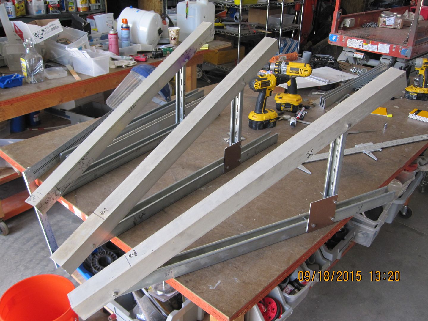
Got the first solar panel of the new bank of 4 installed Saturday late.
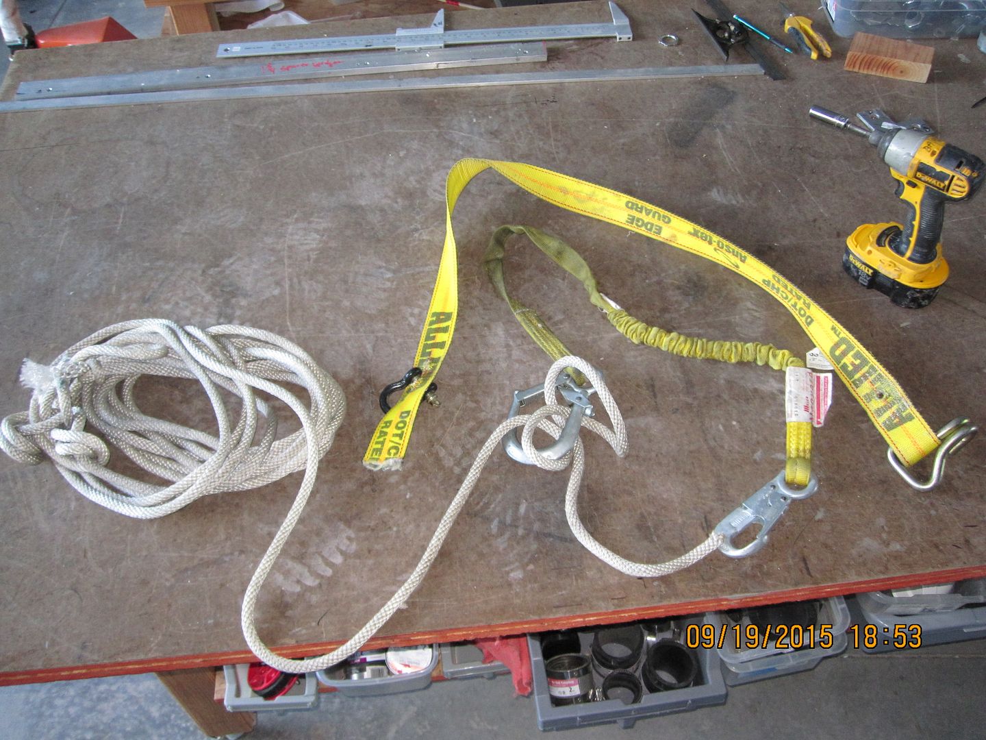
Still had a lot of design issues with the incline mount. Friday the issue was the complex angles that had to be addressed because of the curvature of the bldg. The 1st pix below shows the wedge shim that solved the problem, located between the bldg. and the cross member. 4 wedges reqd's per each panel install. I put grey concrete urethane crack sealer under the wedge and use stainless bolts for a good installation. Next pix shows the 3 assembled supports and the aluminum angle surface is where the panels mount. Mounting hole spacing is about 37 inches sideways and 35 inches up and down. Panel mounting holes get drilled on each end of the aluminum angle. The mount asm in the back is the reference one with all the precise dimensions, etc, so I can make more since the 2 in the front are now way up high and hard to get to. The large Unistrut material bolts to the bldg. arch peaks with the wedges and the thinner Unistrut set's the angle to the sun. I think it's about 25 degrees, but I just winged what I thought would be a good compromise between a lot of variables. In the pix above, I spanned 3 arch peaks with one length of Unistrut It took about a 60" length. I have no recollection why I did this, as it was some years ago. The new mount spans just 2 arch peaks and the Unistrut is abt 37" or something like that. I decided to mount this bank above the 4 existing panels. Too high for a ladder, a man-lift is useless because of the curvature of the roof. The telehandler can't get into the area between the barn and an adjacent bank. So, I had to improvise a climbing harness. I had some nylon 3/4" rope and attached it to one end of the barn above where I was going to work and connected it to some antennas abt 30 feet across the peak away. Pulled it good and tight. Then I looped the small line in the pix around the first line and made a knot so the line could slide lengthways as needed. Then I needed some sort of harness -I thought I had brought one up but didn't, so had to make one. I found a short length of truck strap that had gotten damaged and it seemed to be a good possibility for a belt. Punched 2 holes in it for that chain link thingy to screw through and adj it so it fit snug. There was a safety strap with a large clip on one end and I passed 5 turns of the rope through it. Then when at working location at the panel I'd tie a couple half hitches or whatever to secure it. Worked OK. Was able to get pretty far over the roof and installed the 1st panel of the 2nd bank about 14 IIRC bolt holes above the 1st bank. Some cautions are, the rope is slippery on the metal -don't step on it. Don't allow yourself to become up-ended. the metal bolts and stuff hurt. Don't lower down and rely on the wrong [loose] end of the rope for support Don't get tangled up on rope or stuff. Any fall is going to hurt. 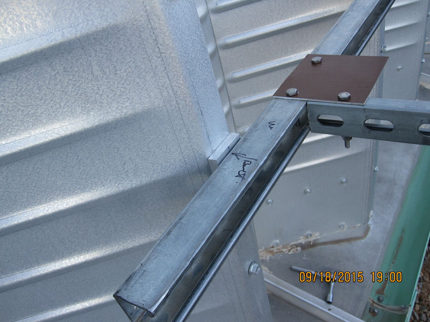
|
|
|
|
[#43]
Just went and looked at yesterday's panel install, looks sort of small up there...
One issue is I should have mtg'ed the panel another arch to the North, as in the winter there is likely to be shading of that panel from another group on the end of the bldg. I'll solve that if so, by either adding a diode across that panel to shunt it, or make some sort of micro-proc to logically short it when the other panels are putting out and it isn't. Also, the spacing between each inclined panel has to be increased by an arch, to minimize shading. There was a guy who won some recognition in the 1800's for inventing the Abney Level. I think his name was Mr. Abney...
Here's what they look like, and are available inexpensively, esp on ebay, be sure not to get one made in China. I've had one made in Japan for decades. PIX Mine's this one I think from Brookstone years ago... 
There's a lot more complex and fancy ones, but for solar work, the simple ones are fine. BTW, here's a Wiki article on them... Wiki--- Abney level These are useful instruments for solar alignment and visualizing angles and shading, etc. There's a manual online I think that goes into the use of the level. These things are so incredibly versatile, you'll find ways to use it no one had dreamed of before. After this group of 4 gets up, then I have to put up another group of 4. I'm tired of this shit already... 
Well, don't have to--- but think I NEED to... Oh, to measure the sun angle in the daytime
Don't point at the sun, point at the shadow of the Abney, and take the same measurement. Another pix. BTW, the level can be placed on a surface to measure it's 'angle' 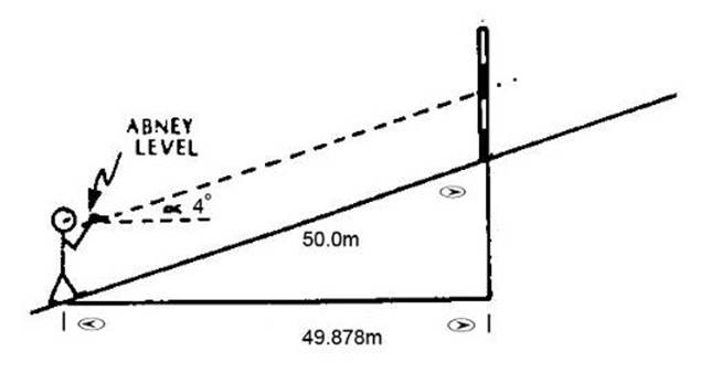
Inventor of the level --Fancy looking dude!! |
|
|
|
[#44]
Looks like your having fun EXPY!
I have 24 panels to put up and haven't made up my mind on how I want to do it. Half the time I want ground mounts so I can play and inspect easily then I think how nice It would be If they were 20' up and protected. I think way too much. I need to retire so it's all I have to do. |
|
|
|
[#45]
Something to mention abt the Abney level...
Most applications are looking thru the sight, and moving the protractor until the bubble is centered. There's another application, look thru the level from the SIDE, not using the tube and peep sight. For example, if you are standing back looking at a panel on a roof and want to know it's slope, hold the level sideways and align the square tube with the slope and move the protractor until the bubble centers. A small mirror helps. You can determine shadows too. Use the NOAA solar calculator, find the angles of the sun at different times of day, then set the protractor to the angle and center the bubble, hold the level sideways and you can visualize the shadow angle or the angle of the suns rays. |
|
|
|
[#46]
Worked all day yesterday making additional mounting components and didn't go on the roof.
Today so far have finished all the components for mtg the next 3 panels, [as well as a few for the next and final group of 4] and will be on the roof in abt 2 hrs. Band saw broke a blade while my SO was cutting material so that slowed us down. Had to realign the blade support bearings. Always one thing or another. Now she's fixing a sammich... Discovered that the first panel I put up, I forgot and turned the lower 2 wedges the same way as the first. So now I have to rework that assembly, and reverse the lower two. Made a 'wrench' out of thick sheet metal -1/8" to turn the sealed wedges. Shouldn't be a big deal to fix. The panels are rather tolerant of small incident angle illumination. From watching the sun direction vs. this new bank, looks like this bank will be a good compromise of alignment between the original 2 banks. |
|
|
|
[#47]
Finished the installation of the 3rd bank of [4] 240 watt panels Thursday.
Tested them with an ammeter for shorted current and read 9.5 amps nominal. The Sharp specs say 8.5 amps. The improvised rope suspension system worked well and the panels couldn't have gotten up without it, at least I don't know how without a big fancy man lift that would have been a real pain to bring up here. I relocated the first panel installed--- away from the original panels that are mt'd to the end of the bldg., one arch distance, about 25 inches. That takes care of the potential winter shading I hope. Fully understand the wedge/angle mounting issue now. There are approx. 126 bolts for a 180 degree arch. There are 6 bolts inclusive the mounts are attached to. Dividing 180/126 gets us ~1.35 degrees 'angle' subtended [? ] between each pair of bolts. Multiplying 6 x 1.35 = 8.1 degrees between 6 bolts, subtended angle in degrees. Since there are two mounting arms sticking out, that means a 4 degree 'tilt' is required per mount with the wide side of the wedge facing away from each other. I measured the angle of the milling setup today and the wedges are milled to 4 degrees, close as I can quickly measure. Wheew! We made another complete set of mounting hardware in the past two days or so, to mount 4 panels above the newly installed 4. I wasn't planning on doing this initially, but since the panels were sitting in the SHTF Trading Inventory, figgered, why not? At the moment, there are 12 panels up, 7 from years ago, and 5 just added. So adding four more bringing the total to 16, we should have plenty of juice to charge the battery bank, even running the network stuff, fridge and freezer, in bd wx. That's abt 3700 watt/hrs and allows for charging batteries even when using my lab, etc. The design of the mtg system worked very well, if anyone is putting up panels and needs to incline them, it might be useful. The aluminum arms are disconnected initially from the gusset plate and laid down. The panel is laid on the relatively flat surface and the mtg screws already installed in the al arms are fit into the panel holes. A couple nuts and washers are installed and the panel raised to the approx. 25 degree incline, and the one bolt for each gusset plate/ inclination arm, is installed. This makes is safer to install the panels on the sloping roof. Pix of them are in a previous post, we fab'd 2 parts on the mill, a small plate with a recess to capture the head of a 5/16 bolt inside the Unistrut, that goes thru the roof, to make it a lot easier to secure, while hanging on a rope. Then the wedge. I made 18 today in an hour. So 16 pieces req'd per 8 mounts and 4 panels. Today we finished everything for 4 more panel mounts and will start to install them tomorrow. The curvature of the roof is much less so no need for the rope suspension. These will go right above the latest 4. Pix soon, I hope, SO hasn't sent the latest we took. I have yet to wire up the latest 4, that can wait til it's raining... Now I'm thinking abt adding 3 panels using the same inclined mounts to the top of a shipping container and feeding the juice to the one we live in [that would make 6 total and double available wattage. No wedges/flat roof... |
|
|
|
[#48]
It took almost 3 days to make the hardware for mtg the last 4 panels, not two days, as it turned out.
Got the final [for now at least] group of 4 panels up. This group was fast to install, as I didn't have to belay from a rope like the last 4. Some pix... Putting on makeshift trucker's strap belt... 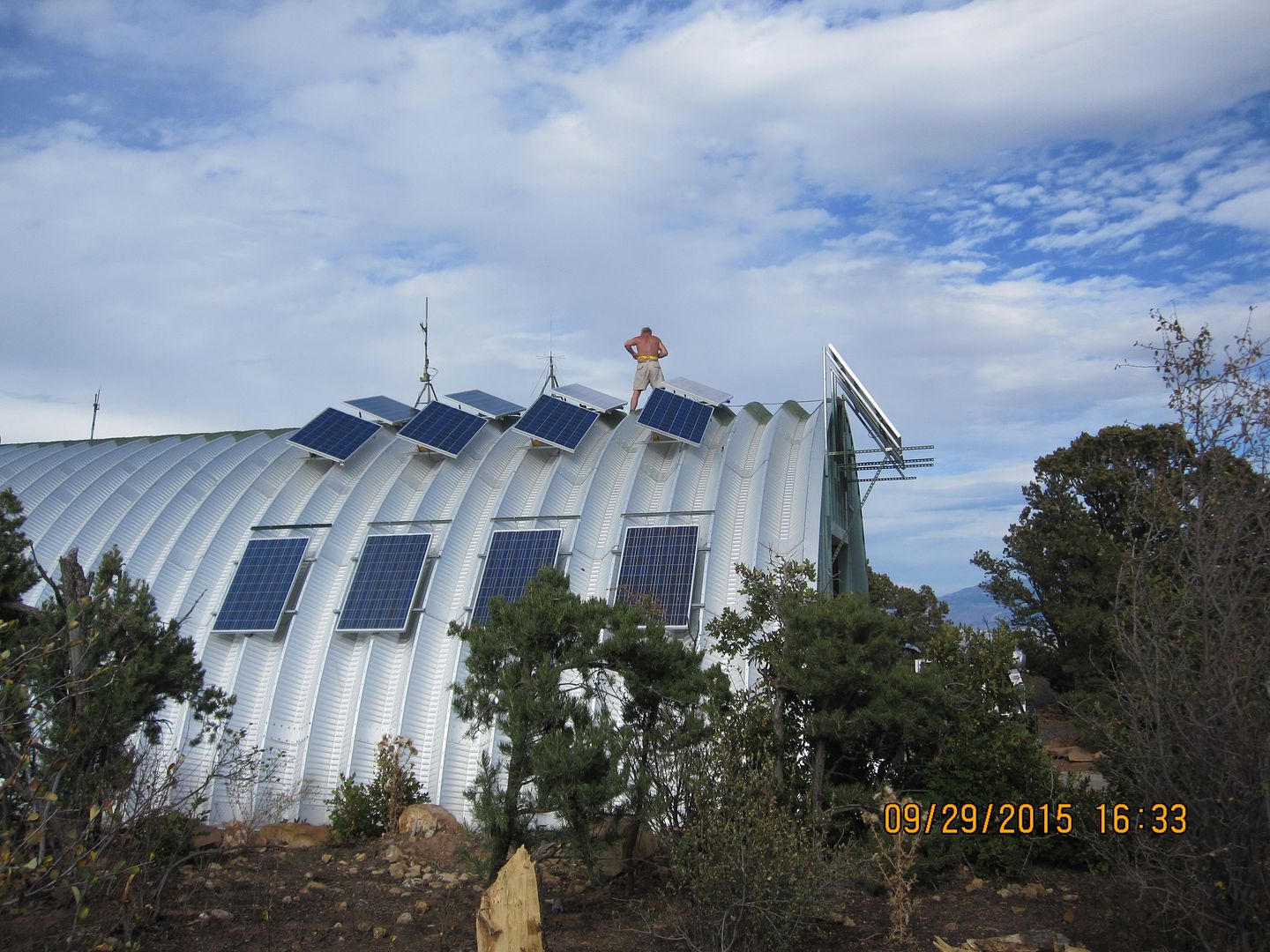
Belayed to change some bolts on the lower first group of 4 installed last week ---to stainless.... 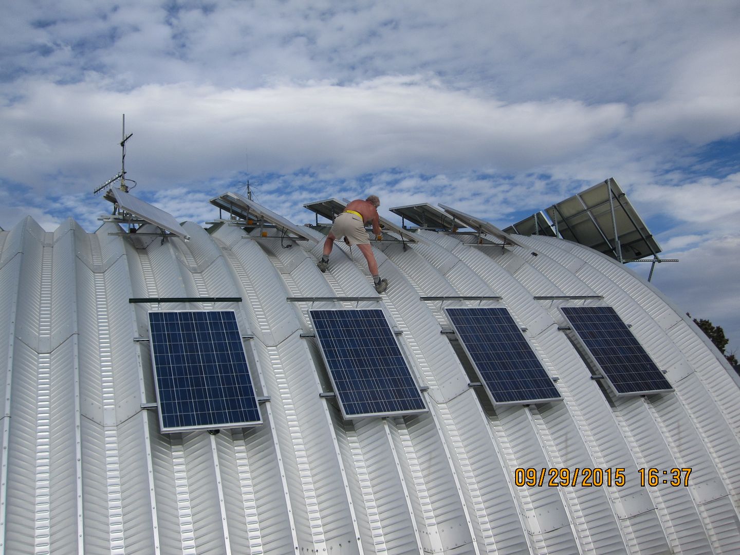
Getting ready to set a panel on a mount. 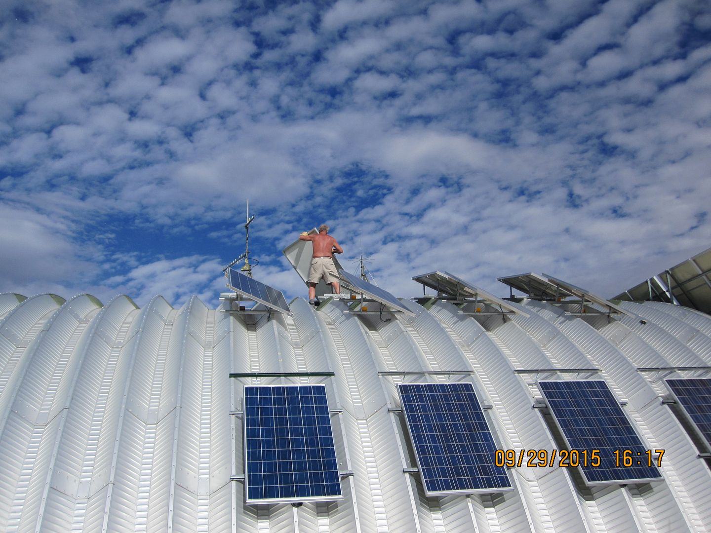
Both recently installed groups. You can see the machined wedges under the Unistrut that solved the curvature/mounting issue. 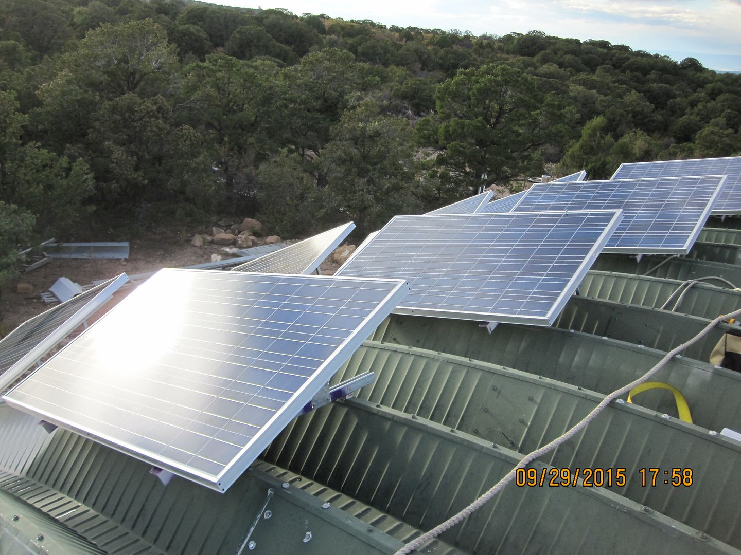
Backside view of the mounting asm's... There's the heavy rope I tie a smaller one off of then wrap 5 turns around the carabineer attached to the trucker's strap that serves as a safety belt/sling. 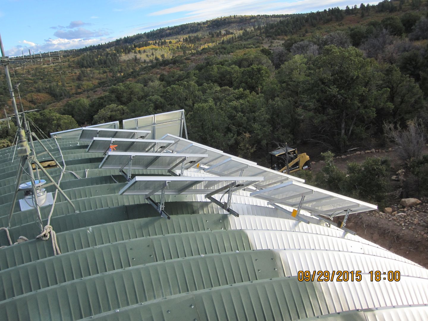
|
|
|
|
[#49]
Nicely done on those mounts, they look great. Beautiful property, too, thanks for posting the pictures.
|
|
|
|
[#50]
Quoted:
Nicely done on those mounts, they look great. Beautiful property, too, thanks for posting the pictures. +1 |
|
|
 Win a FREE Membership!
Sign up for the ARFCOM weekly newsletter and be entered to win a free ARFCOM membership. One new winner* is announced every week!
You will receive an email every Friday morning featuring the latest chatter from the hottest topics, breaking news surrounding legislation, as well as exclusive deals only available to ARFCOM email subscribers.

AR15.COM is the world's largest firearm community and is a gathering place for firearm enthusiasts of all types.
From hunters and military members, to competition shooters and general firearm enthusiasts, we welcome anyone who values and respects the way of the firearm.

Subscribe to our monthly Newsletter to receive firearm news, product discounts from your favorite Industry Partners, and more.
Copyright © 1996-2024 AR15.COM LLC. All Rights Reserved.
Any use of this content without express written consent is prohibited.
AR15.Com reserves the right to overwrite or replace any affiliate, commercial, or monetizable links, posted by users, with our own.


